| DTC Code | DTC Name |
|---|---|
| B1449 | Air Outlet Damper Control Servo Motor Circuit (Rear) |
DESCRIPTION
-
*1: for LHD
-
*2: for RHD
The No. 1 rear cooling unit damper servo sub-assembly (MODE LH)*1 or No. 1 rear cooling unit damper servo sub-assembly (MODE RH)*2 sends pulse signals to inform the air conditioning amplifier assembly of the damper position. The air conditioning amplifier assembly activates the motor (normal or reverse) based on these signals to move the No. 1 rear cooling unit damper servo sub-assembly (MODE LH)*1 or No. 1 rear cooling unit damper servo sub-assembly (MODE RH)*2 to the appropriate position, which controls the air outlet switching.
| DTC No. | Detection Item | DTC Detection Condition | Trouble Area | Memory |
|---|---|---|---|---|
| B1449 | Air Outlet Damper Control Servo Motor Circuit (Rear) |
|
|
Memorized |
| Vehicle Condition | |||
|---|---|---|---|
| Pattern 1 | Pattern 2 | ||
| Diagnosis Condition | During No. 1 rear cooling unit damper servo sub-assembly (MODE LH)*1 or No. 1 rear cooling unit damper servo sub-assembly (MODE RH)*2 operation | ○ | ○ |
| Malfunction Status | The damper servo operation request signal is output but the position information of the servo does not change | ○ | - |
| The damper servo operation request signal is output but the position information of the servo is malfunctioning | - | ○ | |
| Detection Time | Continuously for 30 seconds or more | Continuously for 30 seconds or more | |
| Trip Count | 1 trip | 1 trip | |
If the conditions match either of these patterns, a DTC will be output.
CAUTION / NOTICE / HINT
-
Confirm that no mechanical problem is present because this diagnostic code can be output when either a damper link or the damper is mechanically locked.
-
When installing the damper servo motor, make sure to install it correctly.
-
When the servo motor is replaced, be sure to perform servo motor initialization.
Confirm that no mechanical problem is present because this DTC can be output when either a damper link or damper is mechanically locked.
PROCEDURE
- Click here
CHECK FOR DTC
-
Check for DTCs.
- Body Electrical > Air Conditioner > Trouble Codes
-
-
Result Result Proceed to DTC B1448 is output A DTC B1448 and B149A are output. B
- AClick here
- B
GO TO DTC B149AClick here
-
- Click here
CHECK NO. 1 REAR COOLING UNIT DAMPER SERVO SUB-ASSEMBLY
-
Check for No. 1 rear cooling unit damper servo sub-assembly is installed correctly.
OK No. 1 rear cooling unit damper servo sub-assembly is installed correctly. Result Proceed to OK NG
- OKClick here
- NG
REINSTALL NO. 1 REAR COOLING DAMPER SERVO SUB-ASSEMBLYClick here
-
- Click here
CHECK NO. 1 REAR COOLING DAMPER SERVO SUB-ASSEMBLY (MOTOR, LINK, DAMPER)
-
Check for a wire harness caught between the links of the motors and dampers.
OK No wire harnesses are caught between the links of the motors and dampers. Result Proceed to OK NG
- OKClick here
- NG
REMOVE PINCHED WIRE HARNESS
-
- Click here
CHECK REAR COOLING UNIT ASSEMBLY (DAMPER)
-
Remove the No. 1 rear cooling unit damper servo sub-assembly.
-
Operate the dampers by hand.
OK The dampers are easily operated by hand. Result Proceed to OK NG
- OKClick here
- NG
REPAIR OR REPLACE REAR COOLING UNIT ASSEMBLY
-
- Click here
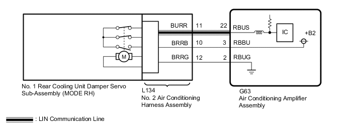
CHECK HARNESS AND CONNECTOR (NO. 2 AIR CONDITIONING HARNESS ASSEMBLY - AIR CONDITIONING AMPLIFIER ASSEMBLY)
-
Disconnect the L134 No. 2 air conditioning harness assembly connector.
-
Disconnect the G63 air conditioning amplifier assembly connector.
-
Measure the resistance according to the value(s) in the table below.
Standard Resistance Tester Connection Condition Specified Condition L134-12 (BRRG) - G63-2 (RBUG) Always Below 1 Ω L134-11 (BURR) - G63-22 (RBUS) Always Below 1 Ω L134-10 (BRRB) - G63-3 (RBBU) Always Below 1 Ω L134-12 (BRRG) or G63-2 (RBUG) - Other terminals and body ground Always 10 kΩ or higher L134-11 (BURR) or G63-22 (RBUS) - Other terminals and body ground Always 10 kΩ or higher L134-10 (BRRB) or G63-3 (RBBU) - Other terminals and body ground Always 10 kΩ or higher Result Proceed to OK NG
- OKClick here
- NG
REPAIR OR REPLACE HARNESS OR CONNECTOR
-
- Click here
PERFORM ACTIVE TEST USING GTS (FOOT A/O SERVO PULSE(D))
-
*1: for LHD
-
*2: for RHD
-
*3: Actually operates the No. 1 rear cooling unit damper servo sub-assembly (MODE LH)*1 or No. 1 rear cooling unit damper servo sub-assembly (MODE RH)*2.
-
Remove the No. 1 rear cooling unit damper servo sub-assembly.
-
for LHD:
-
Connect the No. 1 rear cooling unit damper servo sub-assembly (MODE LH) connector to No. 1 rear cooling unit damper servo sub-assembly (MODE rH).
-
-
for RHD:
-
Connect the No. 1 rear cooling unit damper servo sub-assembly (MODE RH) connector to No. 1 rear cooling unit damper servo sub-assembly (MODE LH).
-
-
Connect the GTS to the DLC3.
-
Turn the power switch on (IG).
-
Turn the GTS on.
-
Enter the following menus: Body Electrical / Air Conditioner / Active Test.
-
Check the operation by referring to the table below.
- Body Electrical > Air Conditioner > Active Test
Tester Display Measurement Item Control Range Diagnostic Note A/O Servo Pulse(Rr P)
- for LHD:
-
No. 1 rear cooling unit damper servo sub-assembly (MODE RH) operation*3
- for RHD:
-
No. 1 rear cooling unit damper servo sub-assembly (MODE LH) operation*3
Min.: 128
Max.: 383
- for LHD:
-
Operates between 237 and 275 pulses
- for RHD:
-
Operates between 234 and 278 pulses
-
-
- Body Electrical > Air Conditioner > Active Test
Tester Display A/O Servo Pulse(Rr P) -
-
-
-
OK No. 1 rear cooling unit damper servo sub-assembly (MODE LH)*1 or No. 1 rear cooling unit damper servo sub-assembly (MODE RH)*2 is operated. Result Proceed to OK NG - Body Electrical > Air Conditioner > Active Test
- OK
REPLACE NO. 2 AIR CONDITIONING HARNESS ASSEMBLYClick here
- NGClick here
-
- Click here
CHECK NO. 1 REAR COOLING DAMPER SERVO SUB-ASSEMBLY
-
Interchange the MODE LH servo motor with MODE RH servo motor and connect the connectors to them.
-
Clear the DTCs.
-
Check for DTCs.
Result Result Proceed to DTC B1489 is output A DTC B1449 is output B DTCs are not output C Tip:Codes other than DTC B1449 and B1489 may be output at this time, but they are not related to this check.
- A
REPLACE NO. 1 REAR COOLING DAMPER SERVO SUB-ASSEMBLYClick here
- B
REPLACE AIR CONDITIONING AMPLIFIER ASSEMBLYClick here
- C
USE SIMULATION METHOD TO CHECKClick here
-