PROCEDURE
- Click here
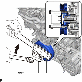
INSTALL TIMING CHAIN CASE OIL SEAL
-
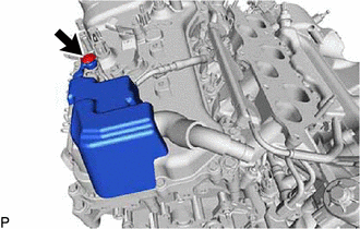
Apply MP grease to the lip of a new timing chain case oil seal.
Note:Keep the lip free of foreign matter.
-
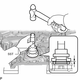
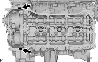
Using SST and a hammer, tap in a new oil seal until its surface is flush with the timing chain cover assembly edge.
09223-22010 09506-35010 Oil Seal Protrusion Height 0 to 1.0 mm (0 to 0.0394 in.) Note:
-
Keep the lip free from foreign matter.
-
Do not tap on the oil seal at an angle.
-
-
- Click here
INSTALL TIMING CHAIN COVER ASSEMBLY
-
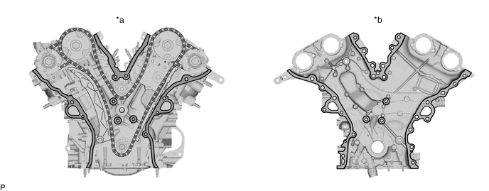
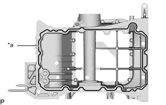
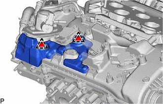
*a Cylinder Head Sub-assembly and Cylinder Block Sub-assembly Side *b Timing Chain Cover Assembly Side 
Clean and Degrease - - Remove any remaining seal packing material and be careful not to drop any oil on the contact surfaces of the timing chain cover assembly, cylinder head sub-assembly and cylinder block sub-assembly.
Note:Be sure to clean and degrease the contact surfaces, especially the surfaces indicated in the illustration.
-
Install the oil pump gasket.
-
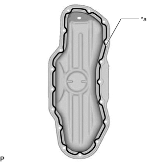
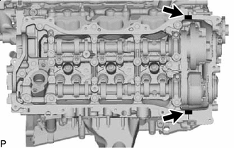
Apply seal packing in a continuous line to the engine unit as shown in the illustration.
-
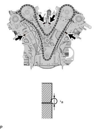
*a Seal Diameter 
Seal Packing Apply seal packing in a continuous line to the engine unit as shown in the illustration.
Seal Packing Toyota Genuine Seal Packing Black, Three Bond 1207B or equivalent Standard Seal Diameter 3.0 to 4.0 mm (0.118 to 0.157 in.) Note:Install the timing chain cover assembly within 3 minutes and tighten the bolts within 10 minutes of applying seal packing.
-
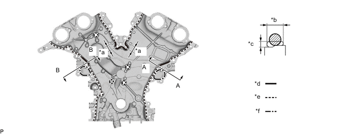
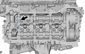
*a 20 mm (0.787 in.) *b 9 mm (0.354 in.) *c 3 mm (0.118 in.) *d Continuous line area (Seal packing: Toyota Genuine Seal Packing Black, Three Bond 1207B or equivalent) *e Dashed line area (Seal packing: Toyota Genuine Seal Packing Black, Three Bond 1207B or equivalent) *f Alternate long and short dashed line area (Seal packing: Toyota Genuine Seal Packing 1282B, Three Bond 1282B or equivalent) Apply seal packing to the timing chain cover sub-assembly in a continuous line as shown in the following illustration.
Note:
-
When the contact surfaces are wet, wipe them with an oil-free cloth before applying seal packing.
-
Install the timing chain cover assembly within 3 minutes and tighten the bolts within 10 minutes after applying seal packing.
Application Specification Area Seal Packing Diameter Application Position from Inside Seal Line Continuous Line Area 4.5 mm (0.177 in.) or more 3.0 to 4.0 mm (0.118 to 0.157 in.) Dashed Line Area 3.5 mm (0.138 in.) or more 3.0 to 4.0 mm (0.118 to 0.157 in.) Alternate Long and Short Dashed Line Area 3.5 mm (0.138 in.) or more 2.0 to 3.0 mm (0.0787 to 0.118 in.) -
-
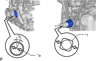
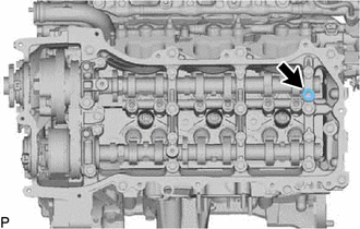
*1 Crankshaft *a Drive Rotor Spline *b 15° Align the oil pump drive rotor spline and crankshaft as shown in the illustration. Install the drive rotor and timing chain cover assembly to the crankshaft.
-
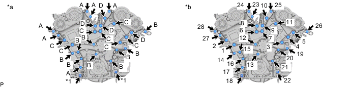
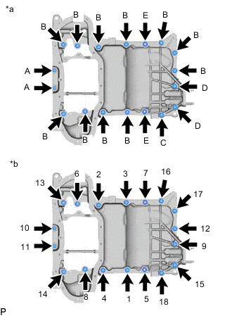
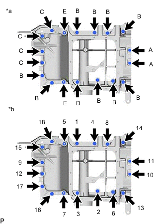
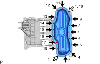
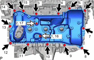
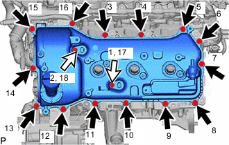
*1 Nut - - *a Types of nut and bolt *b Tightening Order Temporarily install the timing chain cover assembly with the 2 nuts and 26 bolts.
Bolt Length Item Length Bolt A 28 mm (1.10 in.) Bolt B 55 mm (2.17 in.) Bolt C 60 mm (2.36 in.) Bolt D 40 mm (1.57 in.) Note:
-
Make sure that there is no oil on the bolt threads.
-
Do not start the engine for at least 2 hours after installation.
-
Wipe off any seal packing that seeped out around the surfaces of the oil pan sub-assembly and cylinder head cover sub-assembly and make sure that there is no seal packing seeping out around the edges.
-
-
Tighten the 26 bolts and 2 nuts in several steps, in the sequence shown in the illustration.
Bolts A, B and nut 21 N*m 214 kgf*cm 15 ft.*lbf Bolt C and D 43 N*m 438 kgf*cm 32 ft.*lbf
-
- Click here
INSTALL OIL STRAINER SUB-ASSEMBLY
-
Install a new gasket and the oil strainer sub-assembly with the 3 nuts.
10 N*m 102 kgf*cm 7 ft.*lbf
-
- Click here
INSTALL OIL PAN SUB-ASSEMBLY
-
Remove any remaining seal packing material and be careful not to drop any oil on the contact surfaces of the cylinder block sub-assembly, rear oil seal retainer and oil pan sub-assembly.
-
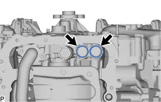
Install 2 new O-rings to the timing chain cover assembly.
-
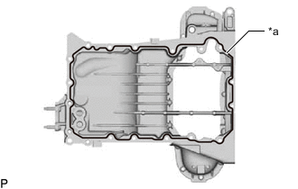
*a Seal Diameter 
Seal Packing for 2WD:
-
Apply seal packing in a continuous line as shown in the illustration.
Seal packing Toyota Genuine Seal Packing Black, Three Bond 1207B or equivalent Standard seal diameter 3.0 to 4.0 mm (0.118 to 0.157 in.) Note:
-
Remove any oil from the contact surface.
-
Install the oil pan sub-assembly within 3 minutes and tighten the bolts within 15 minutes after applying seal packing.
-
Do not add engine oil for at least 2 hours after installation.
-
Do not start the engine within 2 hours after installation.
-
-
*a Types of nut and bolt *b Tightening Order Install the oil pan with the 16 bolts and 2 nuts.
Bolt A 10 N*m 102 kgf*cm 7 ft.*lbf Bolt B, C, D and nut E 21 N*m 214 kgf*cm 15 ft.*lbf Bolt Length Item Length Bolt A 25 mm (0.984 in.) Bolt B 45 mm (1.77 in.) Bolt C 16 mm (0.630 in.) Bolt D 70 mm (2.76 in.)
-
-
*a Seal Diameter Seal Packing for AWD:
-
Apply seal packing in a continuous line as shown in the illustration.
Seal packing Toyota Genuine Seal Packing Black, Three Bond 1207B or equivalent Standard seal diameter 3.0 to 4.0 mm (0.118 to 0.157 in.) Note:
-
Remove any oil from the contact surface.
-
Install the oil pan sub-assembly within 3 minutes and tighten the bolts within 15 minutes after applying seal packing.
-
Do not add engine oil for at least 2 hours after installation.
-
Do not start the engine within 2 hours after installation.
-
-
*a Types of nut and bolt *b Tightening Order Install the oil pan with the 16 bolts and 2 nuts.
Bolt A 10 N*m 102 kgf*cm 7 ft.*lbf Bolt B, C, D and nut E 21 N*m 214 kgf*cm 15 ft.*lbf Bolt Length Item Length Bolt A 25 mm (0.984 in.) Bolt B 45 mm (1.77 in.) Bolt C 16 mm (0.630 in.) Bolt D 70 mm (2.76 in.)
-
-

Wipe off the Seal Packing After tightening the oil pan bolts and nuts, wipe off the seal packing material that has seeped out from between the contact surfaces of the cylinder block sub-assembly and oil pan sub-assembly.
-
- Click here
INSTALL OIL LEVEL SENSOR BRACKET
- Click here
INSTALL ENGINE OIL LEVEL SENSOR
- Click here
INSTALL OIL WITH STRAINER PIPE SUB-ASSEMBLY (for AWD)
-
Install a new gasket and the oil with strainer pipe with the 3 nuts.
10 N*m 102 kgf*cm 7 ft.*lbf
-
- Click here
INSTALL NO. 2 OIL PAN SUB-ASSEMBLY
-
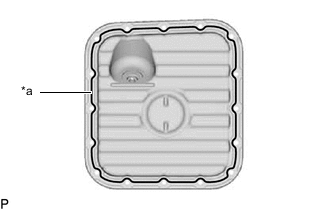
*a Seal Diameter Seal Packing for 2WD:
-
Apply seal packing in a continuous line as shown in the illustration.
Seal packing Toyota Genuine Seal Packing Black, Three Bond 1207B or equivalent Standard seal diameter 3.0 to 4.0 mm (0.118 to 0.157 in.) Note:
-
Remove any oil from the contact surface.
-
Do not start the engine for at least 2 hours after the installation.
-
-
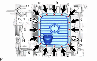
Bolt 
Nut Install the No. 2 oil pan sub-assembly with the 15 bolts and 2 nuts. Tighten the bolts and nuts uniformly in several steps.
10 N*m 102 kgf*cm 7 ft.*lbf Note:
-
Tighten the nuts first. After tightening the bolts, check that the nuts and bolts are tightened to the specified torque.
-
Do not start the engine for at least 2 hours after the installation.
-
-
-
*a Seal Diameter Seal Packing for AWD:
-
Apply seal packing in a continuous line as shown in the illustration.
Seal packing Toyota Genuine Seal Packing Black, Three Bond 1207B or equivalent Standard seal diameter 3.0 to 4.0 mm (0.118 to 0.157 in.) Note:
-
Remove any oil from the contact surface.
-
Do not start the engine for at least 2 hours after the installation.
-
-
Bolt Nut Install the No. 2 oil pan sub-assembly with the 14 bolts and 2 nuts. Tighten the bolts and nuts uniformly in several steps.
10 N*m 102 kgf*cm 7 ft.*lbf Note:
-
Tighten the nuts first. After tightening the bolts, check that the nuts and bolts are tightened to the specified torque.
-
Do not start the engine for at least 2 hours after the installation.
-
-
-
- Click here
INSTALL SPARK PLUG TUBE GASKET
- Click here
INSTALL CYLINDER HEAD COVER SUB-ASSEMBLY
-
Remove any remaining seal packing material and be careful not to drop any oil on the contact surfaces of the cylinder head sub-assembly, timing chain cover assembly and cylinder head cover sub-assembly.
-
Seal Packing 2.0 to 3.0 mm (0.0787 to 0.118 in.) Apply seal packing as shown in the illustration.
Seal packing Toyota Genuine Seal Packing Black, Three Bond 1207B or equivalent Standard seal diameter 2.0 to 3.0 mm (0.0787 to 0.118 in.) Note:
-
Remove any oil from the contact surface.
-
Install the cylinder head cover sub-assembly within 3 minutes and tighten the bolts within 15 minutes after applying seal packing.
-
-
Install 2 new gaskets and a new cylinder head cover gasket.
-
Install a new gasket to the cylinder head cover sub-assembly.
-
Temporarily install the VVT sensor (for exhaust side of bank 1) to the cylinder head cover sub-assembly.
-
Temporarily install the VVT sensor (for intake side of bank 1) to the cylinder head cover sub-assembly.
-
Bolt A Bolt B Temporarily install the cylinder head cover sub-assembly with the 15 bolts. Tighten the bolts uniformly in several steps.
10 N*m 102 kgf*cm 7 ft.*lbf Bolt Length Item Length Bolt A 25 mm (0.984 in.) Bolt B 23.5 mm (0.925 in.) Note:Do not start the engine for at least 2 hours after installation.
-
- Click here
INSTALL CYLINDER HEAD COVER SUB-ASSEMBLY LH
-
Remove any remaining seal packing material and be careful not to drop any oil on the contact surfaces of the cylinder head sub-assembly, timing chain cover assembly and cylinder head cover sub-assembly LH.
-
Seal Packing 2.0 to 3.0 mm (0.0787 to 0.118 in.) Apply seal packing as shown in the illustration.
Seal packing Toyota Genuine Seal Packing Black, Three Bond 1207B or equivalent Standard seal diameter 2.0 to 3.0 mm (0.0787 to 0.118 in.) Note:
-
Remove any oil from the contact surface.
-
Install the cylinder head cover sub-assembly LH within 3 minutes and tighten the bolts within 15 minutes after applying seal packing.
-
-
Install 2 new gaskets and a new cylinder head cover gasket.
-
Install a new camshaft bearing cap oil hole gasket LH.
-
Install a new gasket to the cylinder head cover sub-assembly LH.
-
Temporarily install the VVT sensor (for exhaust side of bank 2) to the cylinder head cover sub-assembly LH.
-
Temporarily install the VVT sensor (for intake side of bank 2) to the cylinder head cover sub-assembly LH.
-
Bolt A Bolt B Temporarily install the cylinder head cover sub-assembly LH with the 16 bolts. Tighten the bolts uniformly in several steps.
10 N*m 102 kgf*cm 7 ft.*lbf Bolt Length Item Length Bolt A 25 mm (0.984 in.) Bolt B 23.5 mm (0.925 in.) Note:Do not start the engine for at least 2 hours after installation.
-
- Click here
INSTALL IGNITION COIL ASSEMBLY
- Click here
INSTALL FUEL PUMP ASSEMBLY (for High Pressure)
- Click here
INSTALL NO. 1 FUEL TUBE SUB-ASSEMBLY
- Click here
INSTALL NO. 1 ENGINE COVER SUB-ASSEMBLY
-
for Bank 1:
Install the No. 1 engine cover to the cylinder head cover sub-assembly with the 2 clips.
-
for Bank 2:
Install the No. 1 engine cover to the cylinder head cover sub-assembly LH with the clip.
-
- Click here
INSTALL CRANKSHAFT PULLEY
-
Align the crankshaft timing gear key with the key groove of the crankshaft pulley, and slide on the crankshaft pulley.
-
*a Hold Turn Using SST to hold the crankshaft pulley in place, tighten the crankshaft pulley set bolt.
09213-70011 09213-70020 09330-00021 260 N*m 2651 kgf*cm 192 ft.*lbf
-
- Click here
INSTALL OIL FILTER BRACKET SUB-ASSEMBLY
-
Install the oil filter bracket sub-assembly and a new gasket with the 2 nuts and 2 bolts.
21 N*m 214 kgf*cm 15 ft.*lbf
-
- Click here
INSTALL CAMSHAFT TIMING OIL CONTROL SOLENOID ASSEMBLY (for Intake Side of Bank 1)
- Click here
INSTALL CAMSHAFT TIMING OIL CONTROL SOLENOID ASSEMBLY (for Exhaust Side of Bank 1)
- Click here
INSTALL CAMSHAFT TIMING OIL CONTROL SOLENOID ASSEMBLY (for Intake Side of Bank 2)
- Click here
INSTALL CAMSHAFT TIMING OIL CONTROL SOLENOID ASSEMBLY (for Exhaust Side of Bank 2)
- Click here
INSTALL WATER OUTLET
- Click here
INSTALL NO. 2 WATER BY-PASS HOSE
- Click here
INSTALL NO. 6 WATER BY-PASS HOSE
- Click here
INSTALL WATER HOSE SUB-ASSEMBLY
- Click here
INSTALL WATER PUMP PULLEY
- Click here
INSTALL NO. 1 WATER BY-PASS PIPE (w/ Oil Cooler)
- Click here
INSTALL V-RIBBED BELT
- Click here
INSTALL INTAKE AIR SURGE TANK ASSEMBLY
- Click here
INSTALL ENGINE WIRE
- Click here
INSTALL ENGINE AND TRANSMISSION