EXHAUST MANIFOLD INSTALLATION

PROCEDURE
-
INSTALL NO. 2 MANIFOLD CONVERTER INSULATOR (for AWD)
-
Exhaust manifold assembly LH side:
-
Install the No. 2 manifold converter insulator to the exhaust manifold assembly with the 3 bolts.
- Torque:
- 10 N*m { 102 kgf*cm, 7 ft.*lbf }
-
-
Exhaust manifold assembly RH side:
-
Install the No. 2 manifold converter insulator to the exhaust manifold assembly with the 4 bolts.
- Torque:
- 10 N*m { 102 kgf*cm, 7 ft.*lbf }
-
-
-
INSTALL NO. 2 MANIFOLD CONVERTER INSULATOR (for 2WD)
-
Install the 2 No. 2 manifold converter insulators to the exhaust manifold assembly with the 8 bolts.
- Torque:
- 10 N*m { 102 kgf*cm, 7 ft.*lbf }
-
-
INSTALL NO. 1 MANIFOLD CONVERTER INSULATOR (for AWD)
-
Install the 2 No. 1 manifold converter insulators to the exhaust manifold assembly with the 8 bolts.
- Torque:
- 10 N*m { 102 kgf*cm, 7 ft.*lbf }
-
-
INSTALL NO. 1 MANIFOLD CONVERTER INSULATOR (for 2WD)
-
Install the 2 No. 1 manifold converter insulators to the exhaust manifold assembly with the 8 bolts.
- Torque:
- 10 N*m { 102 kgf*cm, 7 ft.*lbf }
-
-
INSTALL NO. 1 EXHAUST MANIFOLD HEAT INSULATOR
-
Install the 2 No. 1 exhaust manifold heat insulators to the exhaust manifold assembly with the 6 bolts.
- Torque:
- 10 N*m { 102 kgf*cm, 7 ft.*lbf }
-
-
INSTALL EXHAUST MANIFOLD ASSEMBLY RH (for AWD)
Tech Tips
Perform "Inspection After Repairs" after replacing the air fuel ratio sensor.
-
w/ Canister Pump Module:
-
w/o Canister Pump Module:
-
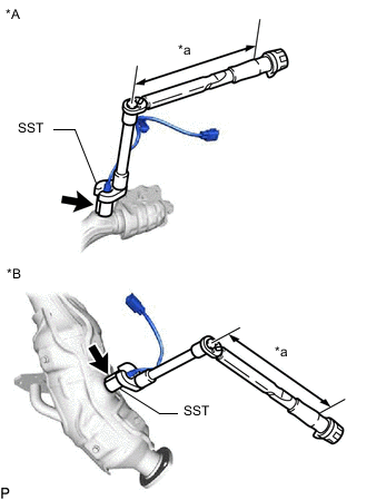
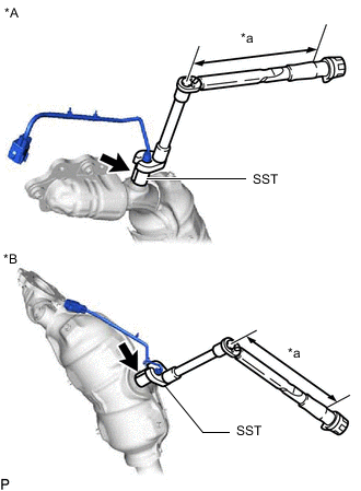
*A Bank 1 Sensor 1 Side *B Bank 1 Sensor 2 Side *a Torque Wrench Fulcrum Length Using SST, install the air fuel ratio sensor to the exhaust manifold assembly RH.
- SST
- 09224-00012
Torque Specified tightening torque 44 N*m (449 kgf*cm, 32 ft.*lbf) Note
Replace with a new part if it is dropped or if it receives a strong impact.
Tech Tips
-
Calculate the torque wrench reading when changing the fulcrum length of the torque wrench.
-
When using SST (fulcrum length of 30 mm (1.18 in.)) + torque wrench (fulcrum length of 180 mm (7.09 in.)): 37.7 N*m (384 kgf*cm, 28 ft.*lbf)
-
Install a new gasket to the cylinder head sub-assembly.
-
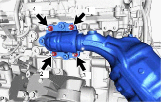
Temporarily install the exhaust manifold assembly RH with 4 new nuts.
-
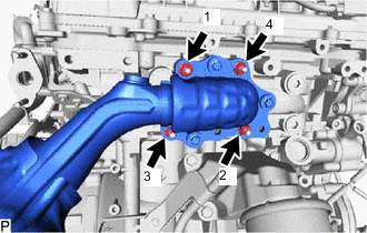
Tighten the 4 nuts in the sequence shown in the illustration.
- Torque:
- 21 N*m { 214 kgf*cm, 15 ft.*lbf }
-
-
INSTALL EXHAUST MANIFOLD ASSEMBLY RH (for 2WD)
Tech Tips
Perform "Inspection After Repairs" after replacing the air fuel ratio sensor.
-
w/ Canister Pump Module:
-
w/o Canister Pump Module:
-
*A Bank 1 Sensor 1 Side *B Bank 1 Sensor 2 Side *a Torque Wrench Fulcrum Length Using SST, install the air fuel ratio sensor to the exhaust manifold assembly RH.
- SST
- 09224-00012
Torque Specified tightening torque 44 N*m (449 kgf*cm, 32 ft.*lbf) Note
Replace with a new part if it is dropped or if it receives a strong impact.
Tech Tips
-
Calculate the torque wrench reading when changing the fulcrum length of the torque wrench.
-
When using SST (fulcrum length of 30 mm (1.18 in.)) + torque wrench (fulcrum length of 180 mm (7.09 in.)): 37.7 N*m (384 kgf*cm, 28 ft.*lbf)
-
Install a new gasket to the cylinder head sub-assembly.
-
Temporarily install the exhaust manifold assembly RH with 4 new nuts.
-
Tighten the 4 nuts in the sequence shown in the illustration.
- Torque:
- 21 N*m { 214 kgf*cm, 15 ft.*lbf }
-
-
INSTALL EXHAUST MANIFOLD ASSEMBLY LH (for AWD)
Tech Tips
Perform "Inspection After Repairs" after replacing the air fuel ratio sensor.
-
w/ Canister Pump Module:
-
w/o Canister Pump Module:
-
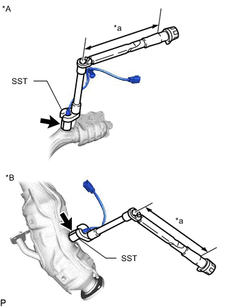
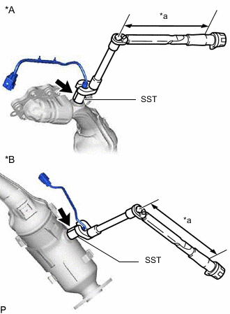
*A Bank 2 Sensor 1 Side *B Bank 2 Sensor 2 Side *a Torque Wrench Fulcrum Length Using SST, install the air fuel ratio sensor to the exhaust manifold assembly LH.
- SST
- 09224-00012
Torque Specified tightening torque 44 N*m (449 kgf*cm, 32 ft.*lbf) Note
Replace with a new part if it is dropped or if it receives a strong impact.
Tech Tips
-
Calculate the torque wrench reading when changing the fulcrum length of the torque wrench.
-
When using SST (fulcrum length of 30 mm (1.18 in.)) + torque wrench (fulcrum length of 180 mm (7.09 in.)): 37.7 N*m (384 kgf*cm, 28 ft.*lbf)
-
Install a new gasket to the cylinder head sub-assembly LH.
-
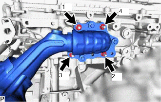
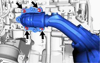
Temporarily install the exhaust manifold assembly LH with 4 new nuts.
-
Tighten the 4 nuts in the sequence shown in the illustration.
- Torque:
- 21 N*m { 214 kgf*cm, 15 ft.*lbf }
-
-
INSTALL EXHAUST MANIFOLD ASSEMBLY LH (for 2WD)
Tech Tips
Perform "Inspection After Repairs" after replacing the air fuel ratio sensor.
-
w/ Canister Pump Module:
-
w/o Canister Pump Module:
-
*A Bank 2 Sensor 1 Side *B Bank 2 Sensor 2 Side *a Torque Wrench Fulcrum Length Using SST, install the air fuel ratio sensor to the exhaust manifold assembly LH.
- SST
- 09224-00012
Torque Specified tightening torque 44 N*m (449 kgf*cm, 32 ft.*lbf) Note
Replace with a new part if it is dropped or if it receives a strong impact.
Tech Tips
-
Calculate the torque wrench reading when changing the fulcrum length of the torque wrench.
-
When using SST (fulcrum length of 30 mm (1.18 in.)) + torque wrench (fulcrum length of 180 mm (7.09 in.)): 37.7 N*m (384 kgf*cm, 28 ft.*lbf)
-
Install a new gasket to the cylinder head sub-assembly LH.
-
Temporarily install the exhaust manifold assembly LH with 4 new nuts.
- Torque:
- 21 N*m { 214 kgf*cm, 15 ft.*lbf }
-
Tighten the 4 nuts in the sequence shown in the illustration.
-
-
TEMPORARILY INSTALL FRONT PROPELLER SHAFT ASSEMBLY (for AWD)
-
TIGHTEN FRONT PROPELLER SHAFT ASSEMBLY (for AWD)
-
CONNECT AIR FUEL RATIO SENSOR
-
for Bank 1 Sensor 1:
-
Connect the connector.
-
Attach the 3 wire harness clamps.
-
-
for Bank 1 Sensor 2:
-
Connect the connector.
-
Attach the 2 wire harness clamps.
-
-
for Bank 2 Sensor 1:
-
Connect the connector.
-
Attach the 4 wire harness clamps.
-
-
for Bank 2 Sensor 2:
-
Connect the connector.
-
Attach the 3 wire harness clamps.
-
-
-
INSTALL NO. 1 EGR PIPE
-
INSTALL FENDER APRON BRACE SUB-ASSEMBLY RH
-
CONNECT GENERATOR CABLE AND MOTOR CABLE
-
INSTALL REAR LOWER ARM MOUNTING REINFORCEMENT SUB-ASSEMBLY RH (for 2WD)
-
Install the rear lower arm mounting reinforcement sub-assembly RH with the 4 bolts.
- Torque:
- 16 N*m { 163 kgf*cm, 12 ft.*lbf }
-
-
INSTALL ENGINE SIDE COVER RH (for 2WD)
-
Attach the clamp, 4 clips and install the engine side cover RH.
-
-
INSTALL NO. 1 EXHAUST PIPE SUPPORT BRACKET SUB-ASSEMBLY
-
Install the No. 1 exhaust pipe support bracket sub-assembly with the 2 bolts.
- Torque:
- 43 N*m { 438 kgf*cm, 32 ft.*lbf }
-
-
INSTALL FRONT EXHAUST PIPE ASSEMBLY
-
INSTALL FRONT CENTER FLOOR BRACE SUB-ASSEMBLY
-
INSTALL FLOOR BOARD SUB-ASSEMBLY
-
INSTALL NO. 2 FLOOR BOARD SUB-ASSEMBLY
-
INSTALL REAR FLOOR SIDE MEMBER COVER RH
-
INSTALL REAR FLOOR SIDE MEMBER COVER LH
-
INSTALL STRUT BAR BRACKET SUPPORT SUB-ASSEMBLY (for AWD)
-
INSTALL FRONT SUSPENSION MEMBER BRACE (for AWD)
-
INSTALL NO. 2 ENGINE UNDER COVER ASSEMBLY (for AWD)
-
INSTALL TRANSMISSION UNDER COVER (for AWD)
-
INSTALL NO. 1 ENGINE UNDER COVER ASSEMBLY (for AWD)
-
INSTALL STRUT BAR BRACKET SUPPORT SUB-ASSEMBLY (for 2WD)
-
INSTALL FRONT SUSPENSION MEMBER BRACE (for 2WD)
-
INSTALL NO. 2 ENGINE UNDER COVER ASSEMBLY (for 2WD)
-
INSTALL TRANSMISSION UNDER COVER (for 2WD)
-
INSTALL NO. 1 ENGINE UNDER COVER ASSEMBLY (for 2WD)
-
INSTALL FRONT APRON FENDER INSULATOR LH
-
Install the front fender apron insulator LH with the 3 bolts.
- Torque:
- 5.4 N*m { 55 kgf*cm, 48 in.*lbf }
-
-
INSTALL ENGINE OIL LEVEL DIPSTICK GUIDE (for AWD)
-
INSTALL NO. 2 ENGINE OIL LEVEL DIPSTICK GUIDE (for 2WD)
-
Install a new O-ring to the No. 2 engine oil level dipstick guide.
-
Install the No. 2 engine oil level dipstick guide with the bolt.
- Torque:
- 21 N*m { 214 kgf*cm, 15 ft.*lbf }
-
Install the engine oil level dipstick to the No. 2 engine oil level dipstick guide.
-
-
INSTALL AIR CLEANER WITH AIR CLEANER HOSE
-
INSTALL NO. 1 AIR CLEANER INLET
-
INSTALL RADIATOR SUPPORT TO CROSSMEMBER BRACE SUB-ASSEMBLY RH
-
Install the radiator support to cross member brace sub-assembly RH with the 2 bolts.
- Torque:
- 49 N*m { 500 kgf*cm, 36 ft.*lbf }
-
-
INSTALL RADIATOR SUPPORT TO CROSSMEMBER BRACE SUB-ASSEMBLY LH
-
Install the radiator support to cross member brace sub-assembly LH with the 2 bolts.
- Torque:
- 49 N*m { 500 kgf*cm, 36 ft.*lbf }
-
-
INSTALL LOWER RADIATOR AIR DEFLECTOR
-
Attach the 7 clips to install the lower radiator air deflector.
-
-
INSTALL UPPER RADIATOR SUPPORT SEAL
-
Attach the 7 clips to install the upper radiator support seal.
-
-
INSTALL RADIATOR COVER PLATE
-
Attach the 7 clips to install the radiator cover plate.
-
-
INSTALL V-BANK COVER SUB-ASSEMBLY
-
INSPECT FOR EXHAUST GAS LEAK