EXHAUST MANIFOLD REMOVAL

CAUTION / NOTICE / HINT
The necessary procedures (adjustment, calibration, initialization or registration) that must be performed after parts are removed and installed, or replaced during air fuel ratio sensor removal/installation are shown below.
| Replaced Part or Performed Procedure | Necessary Procedure | Effect/Inoperative Function when Necessary Procedure not Performed | Link |
|---|---|---|---|
|
Inspection after repairs |
|
|
CAUTION:
-
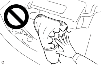
To prevent burns, do not touch the engine, exhaust manifold or other high temperature components while the engine is hot.
-
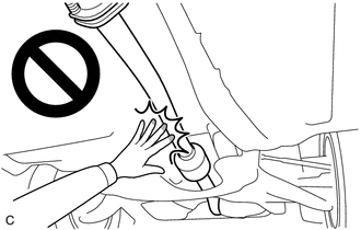
To prevent burns, do not touch the engine, exhaust pipe or other high temperature components while the engine is hot.
PROCEDURE
-
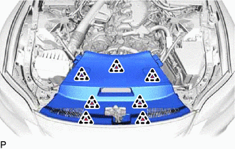
REMOVE V-BANK COVER SUB-ASSEMBLY
-
REMOVE UPPER RADIATOR SUPPORT SEAL
-
Detach the 7 clips to remove the upper radiator support seal.
-
-
REMOVE RADIATOR COVER PLATE
-
Detach the 7 clips to remove the radiator cover plate.
-
-
REMOVE LOWER RADIATOR AIR DEFLECTOR
-
Detach the 7 clips to remove the lower radiator air deflector.
-
-
REMOVE RADIATOR SUPPORT TO CROSSMEMBER BRACE SUB-ASSEMBLY LH
-
Remove the 2 bolts and radiator support to crossmember brace sub-assembly LH.
-
-
REMOVE RADIATOR SUPPORT TO CROSSMEMBER BRACE SUB-ASSEMBLY RH
-
Remove the 2 bolts and radiator support to crossmember brace sub-assembly RH.
-
-
REMOVE NO. 1 AIR CLEANER INLET
-
REMOVE AIR CLEANER WITH AIR CLEANER HOSE
-
REMOVE NO. 2 ENGINE OIL LEVEL DIPSTICK GUIDE (for 2WD)
-
Remove the engine oil level dipstick from the No. 2 engine oil level dipstick guide.
-
Remove the bolt and No. 2 engine oil level dipstick guide.
-
Remove the O-ring from the No. 2 engine oil level dipstick guide.
-
-
REMOVE ENGINE OIL LEVEL DIPSTICK GUIDE (for AWD)
-
REMOVE FRONT FENDER APRON INSULATOR LH
-
Remove the 3 bolts and front fender apron insulator LH.
-
-
REMOVE NO. 1 ENGINE UNDER COVER ASSEMBLY (for 2WD)
-
REMOVE TRANSMISSION UNDER COVER (for 2WD)
-
REMOVE NO. 2 ENGINE UNDER COVER ASSEMBLY (for 2WD)
-
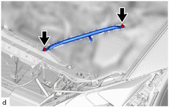
REMOVE FRONT SUSPENSION MEMBER BRACE (for 2WD)
-
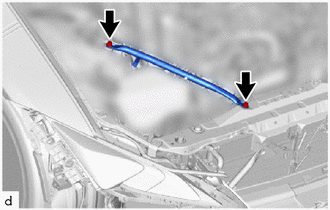
REMOVE STRUT BAR BRACKET SUPPORT SUB-ASSEMBLY (for 2WD)
-
REMOVE NO. 1 ENGINE UNDER COVER ASSEMBLY (for AWD)
-
REMOVE TRANSMISSION UNDER COVER (for AWD)
-
REMOVE NO. 2 ENGINE UNDER COVER ASSEMBLY (for AWD)
-
REMOVE FRONT SUSPENSION MEMBER BRACE (for AWD)
-
REMOVE STRUT BAR BRACKET SUPPORT SUB-ASSEMBLY (for AWD)
-
REMOVE REAR FLOOR SIDE MEMBER COVER LH
-
REMOVE REAR FLOOR SIDE MEMBER COVER RH
-
REMOVE NO. 2 FLOOR BOARD SUB-ASSEMBLY
-
REMOVE FLOOR BOARD SUB-ASSEMBLY
-
REMOVE FRONT CENTER FLOOR BRACE SUB-ASSEMBLY
-
REMOVE FRONT EXHAUST PIPE ASSEMBLY
-
REMOVE NO. 1 EXHAUST PIPE SUPPORT BRACKET SUB-ASSEMBLY
-
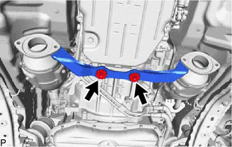
Remove the 2 bolts and No. 1 exhaust pipe support bracket sub-assembly.
-
-
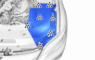
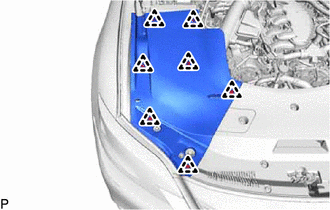
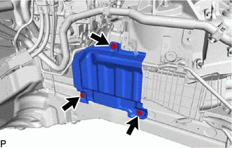
REMOVE ENGINE SIDE COVER RH (for 2WD)
-
Detach the 4 clips to remove the engine side cover RH.
-
-
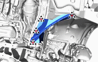
REMOVE REAR LOWER ARM MOUNTING REINFORCEMENT SUB-ASSEMBLY RH (for 2WD)
-

Remove the 4 bolts and rear lower arm mounting reinforcement sub-assembly RH.
-
-
REMOVE FENDER APRON BRACE SUB-ASSEMBLY RH
-
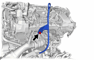
REMOVE NO. 1 EGR PIPE
-
DISCONNECT AIR FUEL RATIO SENSOR
CAUTION:
To prevent burns, do not touch the engine, exhaust pipe or other high temperature components while the engine is hot.
-
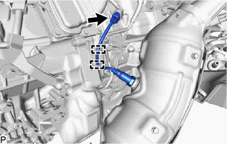
for Bank 1 Sensor 1:
-
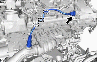
Disconnect the connector.
-
Detach the 3 wire harness clamps.
-
-
for Bank 1 Sensor 2:
-
Disconnect the connector.
-
Detach the 2 wire harness clamps.
-
-
for Bank 2 Sensor 1:
-
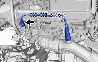
Disconnect the connector.
-
Detach the 4 wire harness clamps.
-
-
for Bank 2 Sensor 2:
-
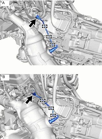
*A for 2WD *B for AWD Disconnect the connector.
-
Detach the 3 wire harness clamps.
-
-
-
REMOVE FRONT PROPELLER SHAFT ASSEMBLY (for AWD)
-
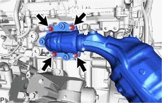
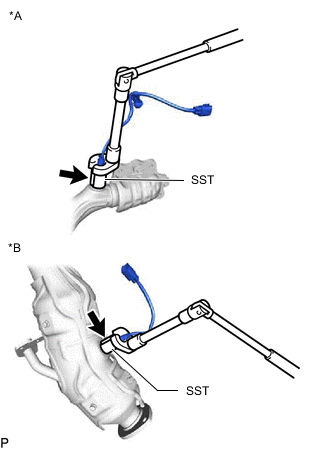
REMOVE EXHAUST MANIFOLD ASSEMBLY LH (for 2WD)
CAUTION:
To prevent burns, do not touch the engine, exhaust pipe or other high temperature components while the engine is hot.
-
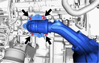
Remove the 4 nuts, exhaust manifold assembly LH and gasket.
-
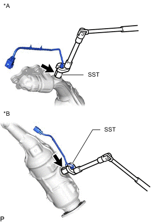
*A Bank 2 Sensor 1 Side *B Bank 2 Sensor 2 Side Using SST, remove the 2 air fuel ratio sensors from the exhaust manifold assembly LH.
- SST
- 09224-00012
-
-
REMOVE EXHAUST MANIFOLD ASSEMBLY LH (for AWD)
CAUTION:
To prevent burns, do not touch the engine, exhaust pipe or other high temperature components while the engine is hot.
-
Remove the 4 nuts, exhaust manifold assembly LH and gasket.
-
*A Bank 2 Sensor 1 Side *B Bank 2 Sensor 2 Side Using SST, remove the 2 air fuel ratio sensors from the exhaust manifold assembly LH.
- SST
- 09224-00012
-
-
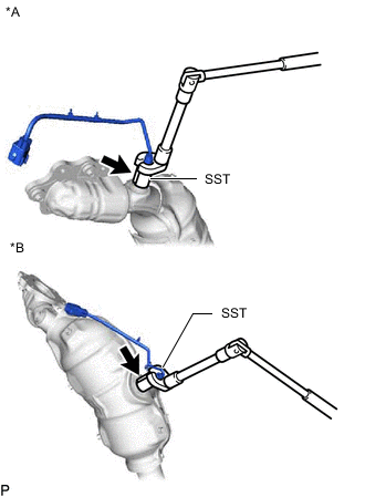
REMOVE EXHAUST MANIFOLD ASSEMBLY RH (for 2WD)
CAUTION:
To prevent burns, do not touch the engine, exhaust pipe or other high temperature components while the engine is hot.
-
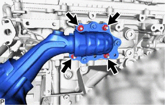
Remove the 4 nuts, exhaust manifold assembly RH and gasket.
-
*A Bank 1 Sensor 1 Side *B Bank 1 Sensor 2 Side Using SST, remove the 2 air fuel ratio sensors from the exhaust manifold assembly RH.
- SST
- 09224-00012
-
-
REMOVE EXHAUST MANIFOLD ASSEMBLY RH (for AWD)
CAUTION:
To prevent burns, do not touch the engine, exhaust pipe or other high temperature components while the engine is hot.
-
Remove the 4 nuts, exhaust manifold assembly RH and gasket.
-
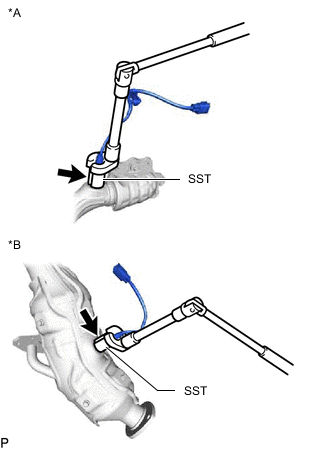
*A Bank 1 Sensor 1 Side *B Bank 1 Sensor 2 Side Using SST, remove the 2 air fuel ratio sensors from the exhaust manifold assembly RH.
- SST
- 09224-00012
-
-
REMOVE NO. 1 EXHAUST MANIFOLD HEAT INSULATOR
-
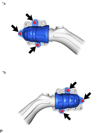
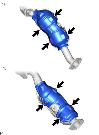
*a Exhaust Manifold Assembly LH Side *b Exhaust Manifold Assembly RH Side Remove the 6 bolts and 2 No. 1 exhaust manifold heat insulators from the exhaust manifold assembly.
-
-
REMOVE NO. 1 MANIFOLD CONVERTER INSULATOR (for 2WD)
-
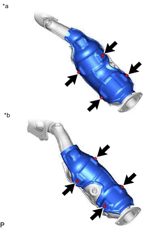
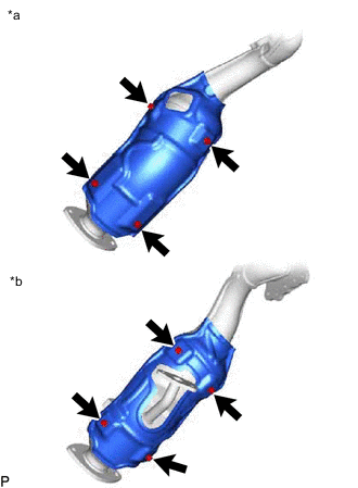
*a Exhaust Manifold Assembly LH Side *b Exhaust Manifold Assembly RH Side Remove the 8 bolts and 2 No. 1 manifold converter insulators from the exhaust manifold assembly.
-
-
REMOVE NO. 1 MANIFOLD CONVERTER INSULATOR (for AWD)
-
*a Exhaust Manifold Assembly LH Side *b Exhaust Manifold Assembly RH Side Remove the 8 bolts and 2 No. 1 manifold converter insulators from the exhaust manifold assembly.
-
-
REMOVE NO. 2 MANIFOLD CONVERTER INSULATOR (for 2WD)
-
*a Exhaust Manifold Assembly LH Side *b Exhaust Manifold Assembly RH Side Remove the 8 bolts and 2 No. 2 manifold converter insulators from the exhaust manifold assembly.
-
-
REMOVE NO. 2 MANIFOLD CONVERTER INSULATOR (for AWD)
-
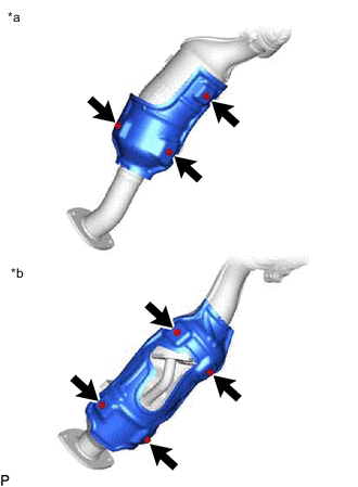
*a Exhaust Manifold Assembly LH Side *b Exhaust Manifold Assembly RH Side Exhaust manifold assembly LH side:
-
Remove the 3 bolts and No. 2 manifold converter insulator from the exhaust manifold assembly.
-
-
Exhaust manifold assembly RH side:
-
Remove the 4 bolts and No. 2 manifold converter insulator from the exhaust manifold assembly.
-
-