INTAKE MANIFOLD REMOVAL
CAUTION / NOTICE / HINT
The necessary procedures (adjustment, calibration, initialization, or registration) that must be performed after parts are removed, installed, or replaced during the camshaft removal/installation are shown below.
| Replaced Part or Performed Procedure | Necessary Procedure | Effect/Inoperative Function when Necessary Procedure not Performed | Link |
|---|---|---|---|
| Auxiliary battery terminal is disconnected/reconnected | Memorize steering angle neutral point | Lane-keeping assist system (for Mono camera type) | for Stereo Camera type: for Mono Camera type: |
| Lane control system (for Stereo camera type) | |||
| Parking support brake system* | |||
| Pre-collision system (for Mono camera type) | |||
| Pre-collision system (for Stereo camera type) | |||
| AFS (Front-lighting adaptive system) | |||
Lighting system (EXT) |
|||
| Variable gear ratio steering system | |||
| Parking assist monitor system | |||
| Panoramic view monitor system | |||
| Initialize rear door sunshade system | Rear door sunshade system | ||
| Initialize power trunk lid system | Power trunk lid system | ||
|
Inspection after repairs |
|
w/ Canister Pump Module w/o Canister Pump Module |
Click here Click here
CAUTION:
-
Orange wire harnesses and connectors indicate high-voltage circuits. To prevent electric shock, always follow the procedure described in the repair manual.
-

To prevent electric shock, wear insulated gloves when working on wire harnesses and components of the high voltage system.
PROCEDURE
-
DISCHARGE FUEL SYSTEM PRESSURE
-
REMOVE THROTTLE BODY WITH MOTOR ASSEMBLY
-
REMOVE INTAKE AIR SURGE TANK ASSEMBLY
-
Disconnect the purge VSV connector.
-
Disconnect the No. 1 fuel vapor feed hose from the intake air surge tank assembly.
-
Remove the bolt to disconnect the purge VSV from the intake air surge tank assembly.
-
Disconnect the vacuum sensor connector.
-
Detach the 3 clamps.
-
Remove the bolt to disconnect the wire harness.
-
Detach the clamp to disconnect the No. 1 fuel tube sub-assembly.
-
for RHD:
Detach the 2 clamps to disconnect the motor cable and generator cable.
-
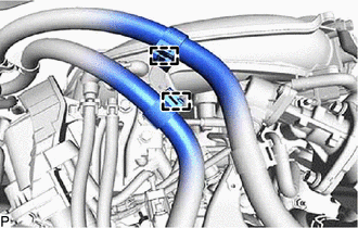
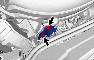
Detach the 2 clamps to disconnect the transmission breather assembly.
-
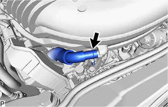
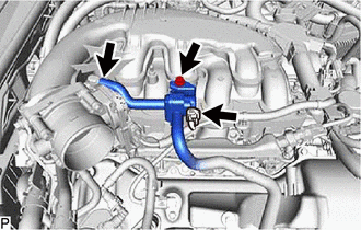
Slide the clamp and disconnect the PCV hose from the intake air surge tank assembly.
-
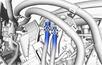
Remove the 2 bolts and No. 2 surge tank stay from the intake air surge tank assembly and camshaft housing sub-assembly LH.
-

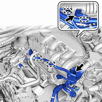
Bolt 
Nut Remove the 2 nuts.
-
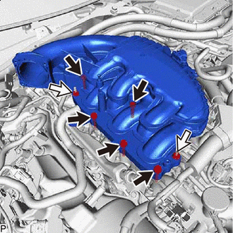
Remove the 5 bolts and intake air surge tank assembly.
-
Remove the air surge tank to intake manifold gasket from the intake air surge tank assembly.
-
-
REMOVE NO. 1 ENGINE COVER SUB-ASSEMBLY
-
REMOVE FUEL TUBE SUB-ASSEMBLY
-
DISCONNECT WIRE HARNESS
-
DISCONNECT FUEL DELIVERY WITH SENSOR PIPE ASSEMBLY
-
DISCONNECT GENERATOR CABLE AND MOTOR CABLE (for LHD)
-
DISCONNECT NO. 15 WATER BY-PASS HOSE
-
REMOVE WATER BY-PASS HOSE
-
REMOVE EGR VALVE ASSEMBLY
-
REMOVE INTAKE MANIFOLD
-
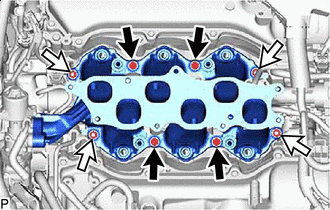
Bolt Nut Remove the 4 bolts, 4 nuts and intake manifold.
-
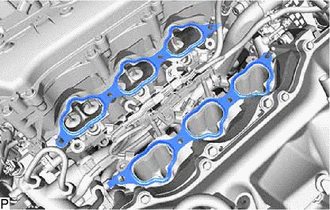
Remove the 2 No. 1 intake manifold to head gaskets.
-
-
REMOVE STUD BOLT
Tech Tips
If a stud bolt is deformed or the threads are damaged, replace it.
-

Using an E8 "TORX" socket wrench, remove the 2 stud bolts from the intake manifold.
-