FUEL TANK PRESSURE SENSOR(w/ Canister Pump Module) REMOVAL
CAUTION / NOTICE / HINT
The necessary procedures (adjustment, calibration, initialization or registration) that must be performed after parts are removed and installed, or replaced during fuel tank pressure sensor(vapor pressure sensor assembly) removal/installation are shown below.
| Replaced Part or Performed Procedure | Necessary Procedure | Effect/Inoperative Function when Necessary Procedure not Performed | Link |
|---|---|---|---|
| Auxiliary battery terminal is disconnected/reconnected | Memorize steering angle neutral point | LKA/LDA system (for Mono camera type) |
|
| Lane control system (for Stereo camera type) | |||
| Parking support brake system* | |||
| Pre-collision system (for Stereo camera type) | |||
| Pre-collision system (for Mono camera type) | |||
| Adaptive high beam system | |||
Lighting system (EXT) |
|||
| Variable gear ratio steering system | |||
| Parking assist monitor system | |||
| Panoramic view monitor system | |||
| Initialize rear door sunshade system | Rear door sunshade system | ||
| Initialize power trunk lid system | Power trunk lid system |
Click here Click here
Note
After turning the power switch off, waiting time may be required before disconnecting the cable from the negative (-) auxiliary battery terminal. Therefore, make sure to read the disconnecting the cable from the negative (-) auxiliary battery terminal notices before proceeding with work.
PROCEDURE
-
REMOVE FUEL TANK ASSEMBLY
-
REMOVE NO. 3 FUEL TANK PROTECTOR
-
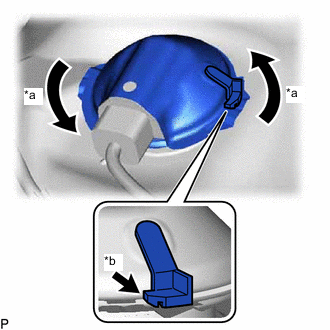
*a Turn *b Lock Release the lock and then turn the No. 3 fuel tank protector, and remove the No. 3 fuel tank protector from the fuel tank protector plate.
-
-
REMOVE REAR FUEL TANK SIDE PLATE SUB-ASSEMBLY
-
Disconnect the connector from the fuel tank pressure sensor.
-
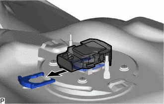
Remove the tube joint clip and fuel tank pressure sensor from the fuel tank evap tube support plate.
Note
-
Before removing the tube joint clip, check for foreign matter around the tube joint clip. Clean if necessary.
-
Keep the O-ring free of foreign matter, as it becomes contaminated easily.
-
Do not use any tools in this procedure.
-
Be careful not to damage the tube joint clip. If the tube joint clip is damaged, replace it.
-
-
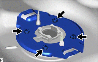
Remove the 4 screws and fuel tank protector plate from the fuel tank assembly.
-
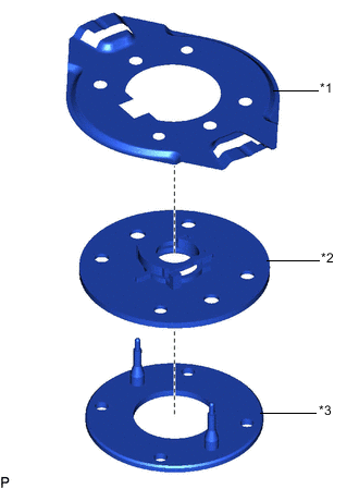
*1 Fuel Tank Protector Plate *2 Fuel Tank Evap Support Plate *3 Gasket Remove the gasket and fuel tank evap tube support plate from the fuel tank protector plate.
-