EGR COOLER REMOVAL
CAUTION / NOTICE / HINT
The necessary procedures (adjustment, calibration, initialization or registration) that must be performed after parts are removed and installed, or replaced during EGR cooler assembly removal/installation are shown below.
| Replaced Part or Performed Procedure | Necessary Procedure | Effect/Inoperative Function when Necessary Procedure not Performed | Link |
|---|---|---|---|
| Auxiliary battery terminal is disconnected/reconnected | Memorize steering angle neutral point | LKA/LDA system (for Mono camera type) |
|
| Lane control system (for Stereo camera type) | |||
| Parking support brake system* | |||
| Pre-collision system (for Stereo camera type) | |||
| Pre-collision system (for Mono camera type) | |||
| Adaptive high beam system | |||
Lighting system (EXT) |
|||
| Variable gear ratio steering system | |||
| Parking assist monitor system | |||
| Panoramic view monitor system | |||
| Initialize rear door sunshade system | Rear door sunshade system | ||
| Initialize power trunk lid system | Power trunk lid system | ||
|
Inspection After Repair |
|
|
Click here Click here
CAUTION:
-
This vehicle has contains high voltage circuits standardized with orange colored wiring and connectors, so follow the instructions in this manual to perform the procedures correctly.
-
If the correct procedures are not followed according to the instructions in this manual, there is a danger of electric shock from the high voltage circuits.
-

Be sure to wear insulating gloves when working on high voltage wiring or components.
-
If work is performed without wearing insulating gloves, there is a danger of electric shock.
-
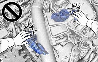
To prevent burns, do not touch the engine, exhaust manifold or other high temperature components while the engine is hot.
PROCEDURE
-
PRECAUTION (for LHD)
Note
After turning the power switch off, waiting time may be required before disconnecting the cable from the negative (-) auxiliary battery terminal. Therefore, make sure to read the disconnecting the cable from the negative (-) auxiliary battery terminal notices before proceeding with work.
-
DISCONNECT CABLE FROM NEGATIVE AUXILIARY BATTERY TERMINAL (for LHD)
Note
When disconnecting the cable, some systems need to be initialized after the cable is reconnected.
-
REMOVE SERVICE PLUG GRIP (for LHD)
-
REMOVE INVERTER COVER ASSEMBLY RH (for LHD)
-
REMOVE CONNECTOR COVER (for LHD)
-
CHECK TERMINAL VOLTAGE (for LHD)
-
TEMPORARILY INSTALL CONNECTOR COVER (for LHD)
-
REMOVE INVERTER TERMINAL COVER (for LHD)
-
DISCONNECT GENERATOR CABLE (for LHD)
-
DISCONNECT MOTOR CABLE (for LHD)
-
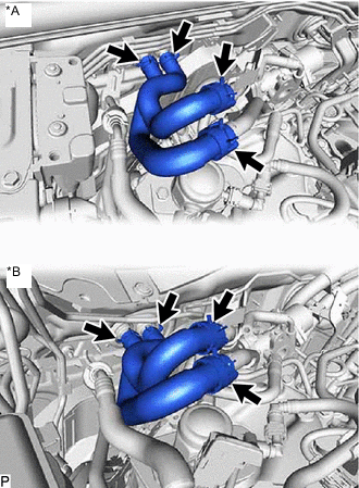
REMOVE INTAKE AIR SURGE TANK ASSEMBLY
-
REMOVE EGR VALVE ASSEMBLY
-
REMOVE INVERTER MOTOR CABLE BRACKET ASSEMBLY (for LHD)
-
Detach the 3 clamps and disconnect the generator cable and motor cable from the inverter motor cable bracket assembly.
-
Remove the 2 bolts and inverter motor cable bracket assembly from the inverter assembly.
-
-
REMOVE FENDER APRON BRACE SUB-ASSEMBLY RH
-
*A for LHD *B for RHD Detach the clamp and disconnect the hose from the fender apron brace sub-assembly RH.
-
Remove the 2 bolts and fender apron brace sub-assembly RH from the body.
-
-
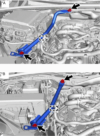
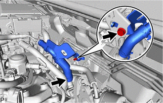
REMOVE INLET HEATER WATER HOSE
-
*A for LHD *B for RHD Slide the 2 clamps and remove the inlet heater water hose from the No. 3 water by-pass pipe and heater pipe.
-
-
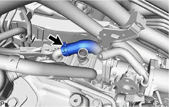
REMOVE OUTLET HEATER WATER HOSE
-
Slide the 2 clamps and remove the outlet heater water hose from the No. 2 water by-pass pipe and heater pipe.
-
-
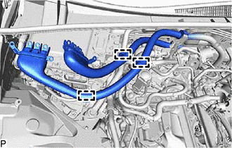
REMOVE NO. 1 EGR PIPE
CAUTION:
To prevent burns, do not touch the engine, exhaust pipe or other high temperature components while the engine is hot.
-
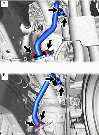
*A for 2WD *B for AWD Remove the 2 bolts, 2 nuts and No. 1 EGR pipe from the exhaust manifold assembly RH and EGR cooler assembly.
-
Remove the 2 gaskets from the No. 1 EGR pipe and EGR cooler assembly.
-
-
REMOVE NO. 4 WATER BY-PASS HOSE
-
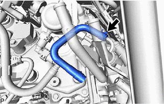
Slide the clamp and remove the No. 4 water by-pass hose from the No. 3 water by-pass pipe.
-
-
REMOVE NO. 3 WATER BY-PASS PIPE
-
for LHD:
Remove the bolt and engine motor cable clamp bracket.
-
Slide the clamp and remove the No. 3 water by-pass pipe from the EGR cooler assembly.
-
-
DISCONNECT NO. 12 WATER BY-PASS HOSE
-
Slide the clamp and disconnect the No. 12 water by-pass hose from the EGR cooler assembly.
-
-
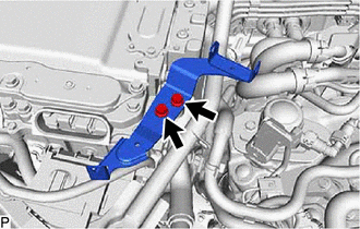
REMOVE EGR COOLER ASSEMBLY
CAUTION:
To prevent burns, do not touch the engine, exhaust pipe or other high temperature components while the engine is hot.
-
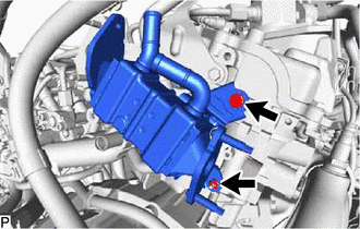
Remove the bolt, nut and EGR cooler assembly from the cylinder head sub-assembly RH.
-