CYLINDER HEAD DISASSEMBLY

CAUTION / NOTICE / HINT
The necessary procedures (adjustment, calibration, initialization, or registration) that must be performed after parts are removed, installed, or replaced during the cylinder head removal/installation are shown below.
| Replaced Part or Performed Procedure | Necessary Procedure | Effect/Inoperative Function when Necessary Procedure not Performed | Link |
|---|---|---|---|
| Auxiliary battery terminal is disconnected/reconnected | Memorize steering angle neutral point | Lane-keeping assist system (for Mono camera type) | for Stereo Camera type: for Mono Camera type: |
| Lane control system (for Stereo camera type) | |||
| Parking support brake system*1 | |||
| Pre-collision system (for Mono camera type) | |||
| Pre-collision system (for Stereo camera type) | |||
| AFS (Front-lighting adaptive system) | |||
Lighting system (EXT) |
|||
| Variable gear ratio steering system | |||
| Parking assist monitor system | |||
| Panoramic view monitor system | |||
| Initialize rear door sunshade system | Rear door sunshade system | ||
| Initialize power trunk lid system | Power trunk lid system | ||
| Replacement of ECM | Vehicle Identification Number (VIN) registration | DTC P063051 is output | w/ Canister Pump Module w/o Canister Pump Module |
|
Inspection after repairs |
|
w/ Canister Pump Module w/o Canister Pump Module |
| Replacement of engine assembly | Inspection after repair | ||
| Drive learning*2 |
|
L310: L310F: |
|
| Parts between the steering wheel and tires have been removed/installed, replaced or adjusted | Perform Actuator Angle Neutral Point Calibration and Initialization |
|
|
| Front bumper assembly (Including removal and installation) |
|
Parking support brake system | |
| Front television camera view adjustment | Panoramic view monitor system | ||
| Suspension, tires, etc |
|
Parking support brake system | |
|
Panoramic view monitor system | ||
| Rear television camera assembly optical axis (Back camera position setting) | Parking assist monitor system |
Click here Click here
*2: After performing the confirmation driving pattern, if the shock during acceleration is large after calibrating the "A/T Code Reset", perform driving learning.
PROCEDURE
-
REMOVE INTAKE VALVE
-
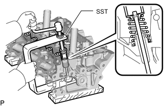
Using SST, compress the inner compression spring and remove the valve spring retainer locks.
- SST
- 09202-70020 ( 09202-01010, 09202-01020 )
- 09202-00021
-
Remove the valve spring retainer, inner compression spring and intake valve.
Tech Tips
Arrange the removed parts in the correct order.
-
-
REMOVE EXHAUST VALVE
-

Using SST, compress the inner compression spring and remove the valve spring retainer locks.
- SST
- 09202-70020 ( 09202-01010, 09202-01020 )
- 09202-00021
-
Remove the valve spring retainer, inner compression spring and exhaust valve.
Tech Tips
Arrange the removed parts in the correct order.
-
-
REMOVE VALVE STEM OIL SEAL
-

Using needle-nose pliers, remove the valve stem oil seals.
-
-
REMOVE VALVE SPRING SEAT
-

Using compressed air and a magnet hand, remove the valve spring seats by blowing air onto them.
-
-
REMOVE NO. 1 STRAIGHT SCREW PLUG
Note
If water leaks from a straight screw plug or the plug is corroded, replace it.
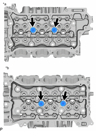
*a for Bank 1 *b for Bank 2
-
Using a 10 mm hexagon wrench, remove the 4 No. 1 straight screw plugs and 4 gaskets.
-
-
REMOVE NO. 2 STRAIGHT SCREW PLUG
Note
If water leaks from a straight screw plug or the plug is corroded, replace it.

*a for Bank 1 *b for Bank 2
-
Using a 14 mm hexagon wrench, remove the 2 No. 2 straight screw plugs and 2 gaskets.
-
-
REMOVE NO. 3 STRAIGHT SCREW PLUG
Note
If water leaks from a straight screw plug or the plug is corroded, replace it.

*a for Bank 1 *b for Bank 2
-
Using a 10 mm hexagon wrench, remove the 8 No. 3 straight screw plugs and 8 gaskets.
-
-
REMOVE UNION
Note
It is not necessary to remove the union unless it is being replaced.
-
REMOVE STUD BOLT
Note
If the stud bolt is deformed or the threads are damaged, replace it.