CYLINDER BLOCK DISASSEMBLY

CAUTION / NOTICE / HINT
The necessary procedures (adjustment, calibration, initialization, or registration) that must be performed after parts are removed, installed, or replaced during the cylinder block removal/installation are shown below.
| Replaced Part or Performed Procedure | Necessary Procedure | Effect/Inoperative Function when Necessary Procedure not Performed | Link |
|---|---|---|---|
| Auxiliary battery terminal is disconnected/reconnected | Memorize steering angle neutral point | Lane-keeping assist system (for Mono camera type) | for Stereo Camera type: for Mono Camera type: |
| Lane control system (for Stereo camera type) | |||
| Parking support brake system*1 | |||
| Pre-collision system (for Mono camera type) | |||
| Pre-collision system (for Stereo camera type) | |||
| AFS (Front-lighting adaptive system) | |||
Lighting system (EXT) |
|||
| Variable gear ratio steering system | |||
| Parking assist monitor system | |||
| Panoramic view monitor system | |||
| Initialize rear door sunshade system | Rear door sunshade system | ||
| Initialize power trunk lid system | Power trunk lid system | ||
| Replacement of ECM | Vehicle Identification Number (VIN) registration | DTC P063051 is output | w/ Canister Pump Module w/o Canister Pump Module |
|
Inspection after repairs |
|
w/ Canister Pump Module w/o Canister Pump Module |
| Replacement of engine assembly | Inspection after repair | ||
| Drive learning*2 |
|
L310: L310F: |
|
| Parts between the steering wheel and tires have been removed/installed, replaced or adjusted | Perform Actuator Angle Neutral Point Calibration and Initialization |
|
|
| Front bumper assembly (Including removal and installation) |
|
Parking support brake system | |
| Front television camera view adjustment | Panoramic view monitor system | ||
| Suspension, tires, etc |
|
Parking support brake system | |
|
Panoramic view monitor system | ||
| Rear television camera assembly optical axis (Back camera position setting) | Parking assist monitor system |
Click here Click here
*2: After performing the confirmation driving pattern, if the shock during acceleration is large after calibrating the "A/T Code Reset", perform driving learning.
PROCEDURE
-
INSPECT CONNECTING ROD THRUST CLEARANCE
-
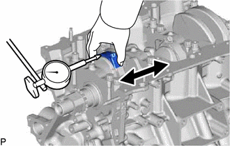
Using a dial indicator, measure the thrust clearance while moving the connecting rod back and forth.
Standard thrust clearance 0.15 to 0.40 mm (0.00591 to 0.0157 in.) Maximum thrust clearance 0.50 mm (0.0197 in.) Tech Tips
If the thrust clearance is more than the maximum, replace the connecting rod sub-assembly. If necessary, replace the crankshaft.
-
-
INSPECT CONNECTING ROD OIL CLEARANCE
-
Check that the matchmarks on the connecting rod sub-assembly and connecting rod cap are aligned.
Tech Tips
The matchmarks on the connecting rod sub-assembly and connecting rod cap are guides for correct reassembly.
-
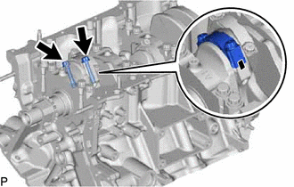
Remove the 2 connecting rod cap bolts.
-
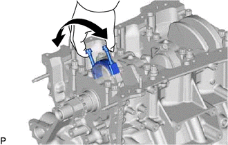
Using the 2 removed connecting rod cap bolts, remove the connecting rod cap and lower bearing by wiggling the connecting rod cap right and left.
Tech Tips
Keep the lower bearing inserted to the connecting rod cap.
-
Clean the crank pin and bearing.
-
Check the crank pin and bearing for pitting and scratches.
-
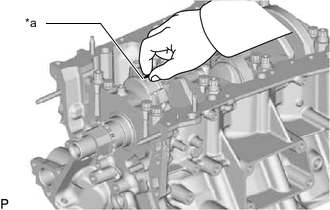
*a Plastigage Lay a strip of Plastigage on the crank pin.
-
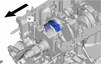
*a Front Mark 
Engine Front Check that the front mark of the connecting rod cap is facing forward.
-
Install the connecting rod cap.
Note
Do not turn the crankshaft.
-
Remove the 2 bolts and connecting rod cap.
-
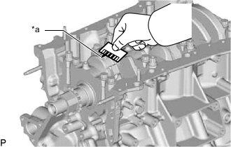
*a Plastigage Measure the Plastigage at its widest point.
Standard oil clearance 0.045 to 0.067 mm (0.00177 to 0.00264 in.) Maximum oil clearance 0.070 mm (0.00276 in.) If the oil clearance is more than the maximum, replace the connecting rod bearings. If necessary, inspect the crankshaft.
Standard Connecting Rod Diameter Mark Specified Condition 1 56.000 to 56.006 mm (2.20472 to 2.20496 in.) 2 56.007 to 56.012 mm (2.20500 to 2.20519 in.) 3 56.013 to 56.018 mm (2.20523 to 2.20543 in.) 4 56.019 to 56.024 mm (2.20547 to 2.20566 in.) Standard Connecting Rod Bearing Center Wall Thickness Mark Specified Condition 1 1.482 to 1.485 mm (0.05835 to 0.05846 in.) 2 1.486 to 1.488 mm (0.05850 to 0.05858 in.) 3 1.489 to 1.491 mm (0.05862 to 0.05870 in.) 4 1.492 to 1.494 mm (0.05874 to 0.05882 in.) Standard crankshaft pin diameter 52.992 to 53.000 mm (2.0863 to 2.0866 in.) Note
Completely remove the Plastigage after the measurement.
-
-
REMOVE PISTON SUB-ASSEMBLY WITH CONNECTING ROD
-
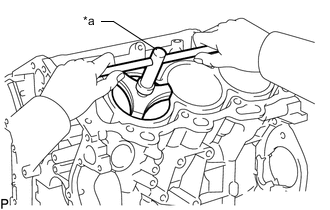
*a Ridge Reamer Using a ridge reamer, remove all the carbon from the top of the cylinder.
-
Push the piston, connecting rod assembly and upper bearing through the top of the cylinder block.
Tech Tips
-
Keep the bearing, connecting rod and cap together.
-
Arrange the piston and connecting rod assemblies in the correct order.
-
-
-
REMOVE CONNECTING ROD BEARING
-
Remove the connecting rod bearings from the connecting rods and connecting rod caps.
Tech Tips
Arrange the removed parts in the correct order.
-
-
REMOVE CRANKSHAFT
-
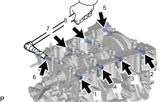
Uniformly loosen and remove the 8 crankshaft bearing cap bolts and 8 seal washers in several steps and in the sequence shown in the illustration.
-
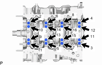
Uniformly loosen the 16 crankshaft bearing cap bolts in several steps and in the sequence shown in the illustration.
-
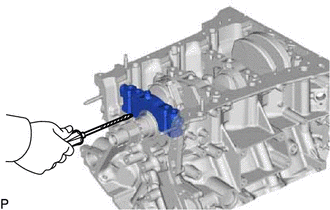
Using a screwdriver, pry out the crankshaft bearing caps. Remove the 4 crankshaft bearing caps and lower crankshaft bearings.
Note
-
Push up on the cap slowly and evenly, alternating from the right and left side so that the bearing cap can be removed.
-
Be careful not to damage the joint surfaces of the cylinder block and the crankshaft bearing cap.
-
-
Remove the crankshaft.
-
-
REMOVE CRANKSHAFT BEARING
-
Remove the upper crankshaft bearings and lower crankshaft bearings.
Tech Tips
Arrange the removed parts in the correct order.
-
-
REMOVE CRANKSHAFT THRUST WASHER SET
-
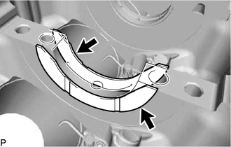
Remove the upper crankshaft thrust washers from the cylinder block sub-assembly.
-
-
REMOVE PISTON RING SET
-
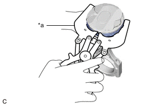
*a Piston Ring Expander Using a piston ring expander, remove the 2 compression rings.
-
Remove the oil ring expander and 2 side rails by hand.
Tech Tips
Arrange the removed parts in the correct order.
-
-
REMOVE PISTON SUB-ASSEMBLY WITH PIN
-
Disconnect the connecting rod from the piston.
-
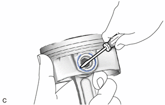
Using a screwdriver, pry off the piston pin hole snap rings from the piston.
-
Gradually heat the piston to approximately 80°C (176°F).
-
Using a brass bar and a plastic-faced hammer, lightly tap out the piston pin and remove the connecting rod sub-assembly.
Tech Tips
-
The piston and piston pin are a matched set.
-
Arrange the pistons, piston pins, connecting rods and connecting rod bearings in the correct order.
-
-
-
Using a gasket scraper, remove the carbon from the piston top.
-
Using a groove cleaning tool or broken ring, clean the piston ring grooves.
-
Using solvent and a brush, thoroughly clean the piston.
Note
Do not use a wire brush.
-
-
REMOVE NO. 1 OIL NOZZLE SUB-ASSEMBLY
-
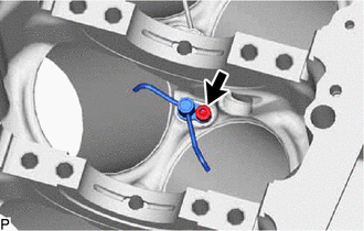
Using a 5 mm hexagon wrench, remove the 3 bolts and No. 1 oil nozzle sub-assemblies.
-
Check the 3 No. 1 oil nozzle sub-assemblies for damage or clogging.
If necessary, replace the No. 1 oil nozzle sub-assembly.
-
-
REMOVE CONNECTING ROD SMALL END BUSH
-
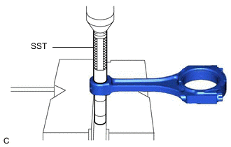
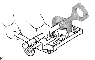
Using SST and a press, press out the connecting rod small end bush.
- SST
- 09222-30010
-