CAUTION / NOTICE / HINT
The necessary procedures (adjustment, calibration, initialization, or registration) that must be performed after parts are removed and installed, or replaced during battery blower removal/installation are shown below.
| Replacement Part or Procedure | Necessary Procedure | Effect/Inoperative when not Performed | Link |
|---|---|---|---|
| Disconnect cable from negative auxiliary battery terminal | Memorize steering angle neutral point | LKA/LDA system (for Mono camera type) | for Stereo Camera type:Click here for Mono Camera type:Click here |
| Lane control system (for Stereo camera type) | |||
| Parking support brake system* | |||
| Pre-collision system (for Mono camera type) | |||
| Pre-collision system (for Stereo camera type) | |||
| Adaptive high beam system | |||
|
|||
| Variable gear ratio steering system | |||
| Parking assist monitor system | |||
| Panoramic view monitor system | |||
| Initialize rear door sunshade system | Rear door sunshade system | ||
| Initialize power trunk lid system | Power trunk lid system | ||
| HV battery |
|
Warning light illumination | |
| DRS ECU (rear steering control ECU) | Perform neutral position memorization and motor rotation angle sensor calibration |
|
|
|
Initialize position control ECU | Rear power seat control system |
-
Orange wire harnesses and connectors indicate high-voltage circuits. To prevent electric shock, always follow the procedure described in the repair manual.
-

To prevent electric shock, wear insulated gloves when working on wire harnesses and components of the high voltage system.
PROCEDURE
- Click here
PRECAUTION
- Click here
REMOVE HV BATTERY ASSEMBLY
- Click here
REMOVE UPPER HV BATTERY COVER PANEL
- Click here
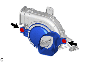
REMOVE BATTERY COOLING BLOWER ASSEMBLY
CAUTION:Be sure to wear insulated gloves and protective goggles.
-
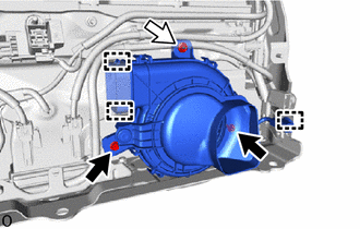
Detach the clamp.
-
Remove the 2 bolts and nut.
-
Disconnect the 2 fittings on the No. 6 hybrid battery intake duct and remove the battery cooling blower assembly.
-
- Click here
REMOVE NO. 5 HYBRID BATTERY INTAKE DUCT
-
Remove the 2 clips and No. 5 hybrid battery intake duct.
-