HV BATTERY INSTALLATION

PROCEDURE
-
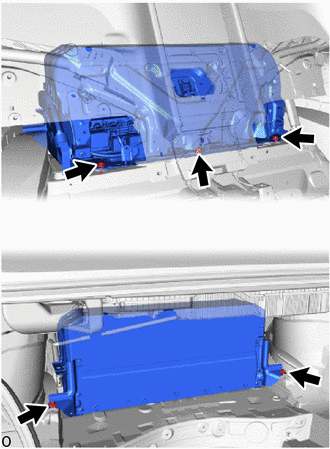
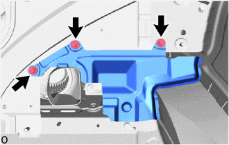
INSTALL NO. 9 HV BATTERY SHIELD PANEL
CAUTION:
Wear insulated gloves.
-
Install the No. 9 HV battery shield panel with the 4 nuts.
- Torque:
- 7.5 N*m { 76 kgf*cm, 66 in.*lbf }
-
-
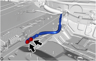
INSTALL HV BATTERY DUCT SUB-ASSEMBLY
CAUTION:
Wear insulated gloves.
-
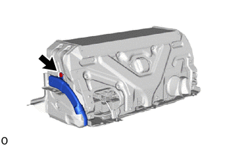
Install the HV battery duct sub-assembly with the clip.
-
-
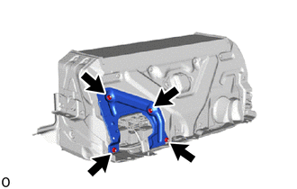
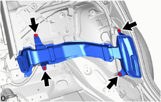
INSTALL HV BATTERY ASSEMBLY
CAUTION:
Wear insulated gloves.
-
Install the HV battery assembly with the 3 bolts and 2 nuts.
- Torque:
- 20 N*m { 204 kgf*cm, 15 ft.*lbf }
Note
-
Do not allow foreign matter, such as grease or oil, to adhere to the bolts of the HV battery.
-
To prevent the wire harness from being caught, make sure to bundle the wire harness using insulating tape or equivalent.
-
Use cardboard or another similar material to protect the HV battery and vehicle body from damage.
-
Since the HV battery is very heavy, 2 people are needed to remove it. When removing the HV battery, be careful not to damage the parts around it.
-
When removing/installing/moving the HV battery, make sure not to tilt it more than 80°.
-
If the HV battery has been struck or dropped, replace it.
-
-
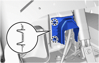
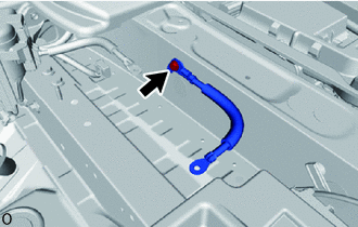
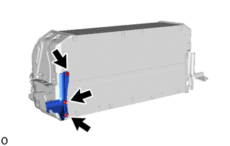
INSTALL NO. 4 HV BATTERY EXHAUST DUCT
CAUTION:
Wear insulated gloves.
-
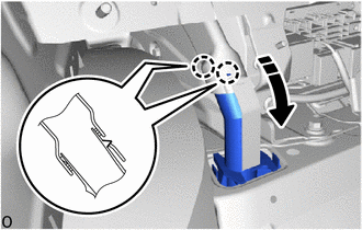
Install the No. 4 HV battery exhaust duct.
-
Attach the 2 claws as shown in the illustration.
-
-
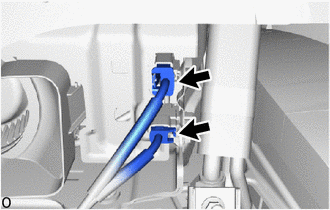
CONNECT HV FLOOR UNDER WIRE
CAUTION:
Wear insulated gloves.
-
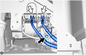
Connect the 2 connectors and install the nut.
- Torque:
- 8.0 N*m { 82 kgf*cm, 71 in.*lbf }
-
-
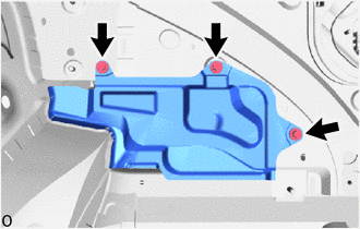
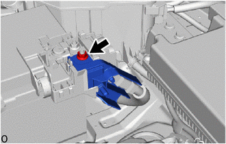
INSTALL NO. 10 HV BATTERY SHIELD PANEL
CAUTION:
Wear insulated gloves.
-
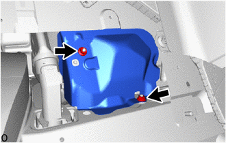
Install the No. 10 HV battery shield panel with the 2 nuts.
- Torque:
- 7.5 N*m { 76 kgf*cm, 66 in.*lbf }
-
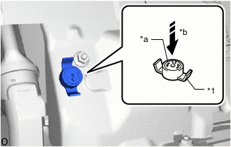
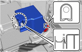
*1 Battery Cover Lock Striker *a Button *b Push Install the battery cover lock striker, then push the button to lock it.
-
-
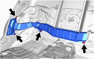
INSTALL CENTER NO. 1 FLOOR TO BLACE EXTENSION
-
Install the center No. 1 floor to blace extension with the 3 bolts.
- Torque:
- 9.8 N*m { 100 kgf*cm, 87 in.*lbf }
-
-
CONNECT FLOOR WIRE
CAUTION:
Wear insulated gloves.
-
Connect the 2 connectors.
-
Attach the 2 claws and install the connector cover.
-
-
INSTALL CENTER NO. 2 FLOOR TO BRACE EXTENSION
-
Install the center No. 2 floor to blace extension with the 3 bolts.
- Torque:
- 9.8 N*m { 100 kgf*cm, 87 in.*lbf }
-
-
INSTALL NO. 1 SEAT RECLINING ADJUSTER ASSEMBLY LH (for Power Seat)
-
INSTALL NO. 1 SEAT RECLINING ADJUSTER ASSEMBLY RH (for Power Seat)
-
INSTALL CENTER ROOM PARTITION GARNISH ASSEMBLY (for Power Seat)
-
INSTALL NO. 4 HYBRID BATTERY INTAKE DUCT
-
Install the No. 4 hybrid battery intake duct with the 4 clips.
-
-
INSTALL NO. 2 EV BATTERY INTAKE DUCT
-
Install the No. 2 EV battery intake duct with the 4 clips.
-
-
INSTALL ROOM PARTITION BOARD ASSEMBLY RH (for Power Seat)
-
INSTALL ROOM PARTITION BOARD ASSEMBLY LH (for Power Seat)
-
INSTALL REAR SEAT SIDE GARNISH RH
-
INSTALL REAR SEAT SIDE GARNISH LH
-
INSTALL REAR DOOR SCUFF PLATE RH
-
INSTALL REAR DOOR SCUFF PLATE LH
-
INSTALL REAR COOLING UNIT ASSEMBLY (w/ Rear Air Conditioning System)
-
INSTALL REAR CENTER SEAT ARMREST ASSEMBLY (for Power Seat)
-
INSTALL REAR SEATBACK ASSEMBLY LH (for Power Seat)
-
INSTALL REAR SEATBACK ASSEMBLY RH (for Power Seat)
-
INSTALL REAR SEAT CUSHION LOCK HOOK (for Power Seat)
-
INSTALL REAR CENTER SEAT CUSHION ASSEMBLY (for Power Seat)
-
INSTALL REAR SEAT CUSHION ASSEMBLY LH (for Power Seat)
-
INSTALL REAR SEAT CUSHION ASSEMBLY RH (for Power Seat)
-
INSTALL REAR SEAT BACK HOLDER (for Fixed Seat Type)
-
INSTALL REAR SEATBACK ASSEMBLY (for Fixed Seat Type)
-
INSTALL NO. 1 SEAT ARMREST CAP (for Fixed Seat Type)
-
INSTALL REAR SEAT CUSHION LOCK HOOK (for Fixed Seat Type)
-
INSTALL REAR SEAT CUSHION ASSEMBLY (for Fixed Seat Type)
-
INSTALL NO. 1 LUGGAGE ROOM WIRE
-
Connect the each connector and install the No. 1 luggage room wire.
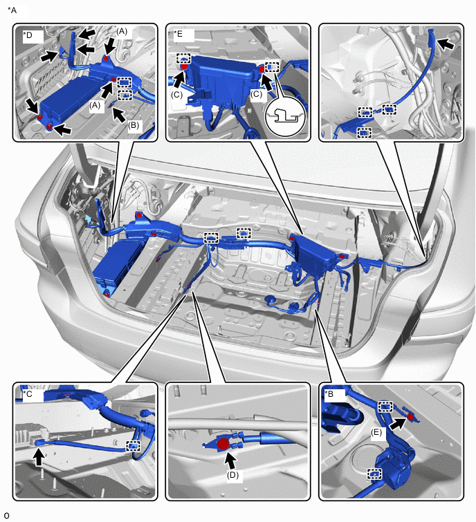
*A w/ Air Suspension *B w/ Dynamic Rear Steering *C w/ 100W Voltage Inverter *D Relay Block A *E Relay Block B - - 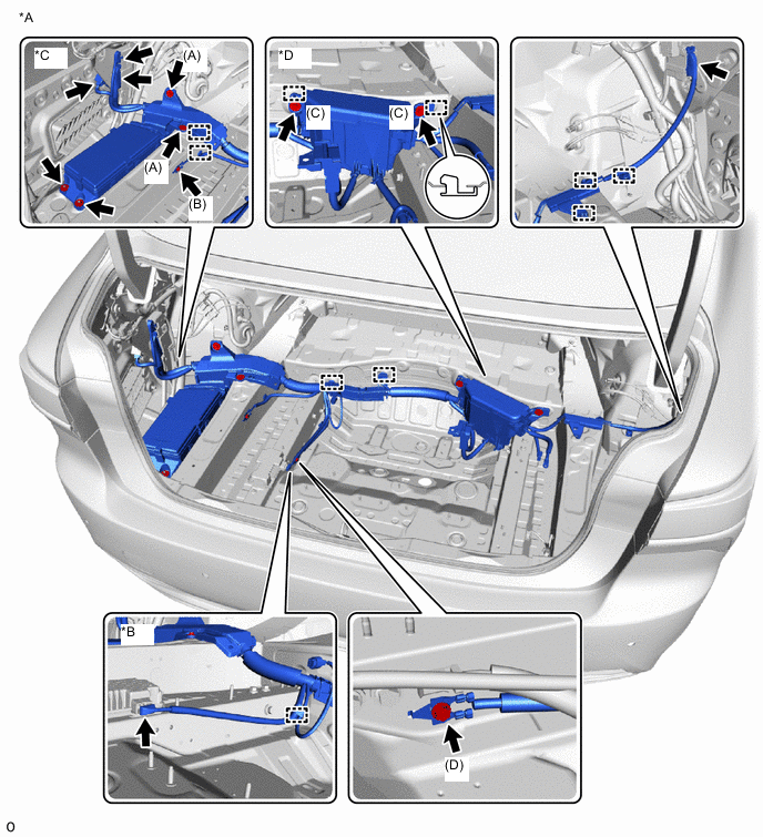
*A w/o Air Suspension *B w/ 100W Voltage Inverter *C Relay Block A *D Relay Block B -
Install the bolt (D).
- Torque:
- Bolt (D)
- 10 N*m { 102 kgf*cm, 7 ft.*lbf }
-
Relay Block B:
-
Install the 2 bolts (C).
- Torque:
- Bolt (C)
- 8.0 N*m { 82 kgf*cm, 71 in.*lbf }
-
-
Relay Block A:
-
Install the 2 bolts (A), bolt (B) and 2 nuts.
- Torque:
- Bolt (A)
- 8.0 N*m { 82 kgf*cm, 71 in.*lbf }
- Bolt (B)
- 10 N*m { 102 kgf*cm, 7 ft.*lbf }
- Nut
- 8.0 N*m { 82 kgf*cm, 71 in.*lbf }
-
-
w/ 100W Voltage Inverter:
-
Connect the connector.
-
Attach the clamp.
-
-
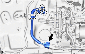
w/ Dynamic Rear Steering:
-
Install the bolt (E).
- Torque:
- Bolt E:
- 10 N*m { 102 kgf*cm, 7 ft.*lbf }
-
Attach the clamp.
-
-
w/ Air Suspension:
-
Attach the clamp and 3 claws.
-
Connect the connector to height control compressor.
-
-
-
INSTALL REAR STEERING CONTROL ECU (w/ Dynamic Rear Steering)
-
INSTALL BATTERY CARRIER ASSEMBLY
-
INSTALL BATTERY CARRIER CATCH BRACKET SUB-ASSEMBLY
-
INSTALL EARTH WIRE
-
Install the earth wire with the 2 bolts.
- Torque:
- 29.35 N*m { 299 kgf*cm, 22 ft.*lbf }
-
-
INSTALL AUXILIARY BATTERY
-
INSTALL NO. 3 EARTH WIRE
-
Install the No. 3 earth wire with the bolt.
- Torque:
- 10 N*m { 102 kgf*cm, 7 ft.*lbf }
-
-
INSTALL SUB-BATTERY MODULE ASSEMBLY
-
CONNECT HV FLOOR UNDER WIRE
-
Connect the HV floor under wire with the nut.
- Torque:
- 7.55 N*m { 77 kgf*cm, 67 in.*lbf }
-
Attach the claw and install the battery terminal cover.
-
-
INSTALL SERVICE PLUG GRIP
-
INSTALL HV BATTERY BRACKET LH
CAUTION:
Wear insulated gloves.
-
Install the HV battery bracket LH with the bolt and 2 nuts.
- Torque:
- 7.5 N*m { 76 kgf*cm, 66 in.*lbf }
-
-
INSTALL COWL TOP VENTILATOR LOUVER SUB-ASSEMBLY
-
INSTALL INVERTER COVER ASSEMBLY RH (for LHD)
-
INSTALL INVERTER COVER ASSEMBLY LH (for RHD)
-
INSTALL REAR LUGGAGE COMPARTMENT TRAY BRACKET RH
-
INSTALL REAR LUGGAGE COMPARTMENT TRAY BRACKET LH
Tech Tips
Perform the same procedure as for the RH side.
-
INSTALL LUGGAGE COMPARTMENT TRIM COVER ASSEMBLY LH
-
INSTALL LUGGAGE COMPARTMENT TRIM COVER ASSEMBLY RH
-
INSTALL FRONT LUGGAGE COMPARTMENT TRIM COVER (w/o Rear Air Conditioning System)
-
INSTALL FRONT LUGGAGE COMPARTMENT TRIM COVER (w/ Rear Air Conditioning System)
-
INSTALL REAR LUGGAGE COMPARTMENT TRIM COVER
-
INSTALL NO. 1 LUGGAGE COMPARTMENT LIGHT ASSEMBLY
-
INSTALL LOWER INNER LUGGAGE COMPARTMENT TRIM COVER
-
INSTALL REAR FLOOR FINISH PLATE
-
INSTALL SIDE TRIM BOX
-
INSTALL LUGGAGE COMPARTMENT TRIM COVER LH
-
INSTALL LUGGAGE COMPARTMENT TRIM COVER RH
-
INSTALL LUGGAGE COMPARTMENT FLOOR MAT
-
INSTALL TOOL BOX
-
CONNECT CABLE TO NEGATIVE AUXILIARY BATTERY TERMINAL
Note
When disconnecting the cable, some systems need to be initialized after the cable is reconnected.
-
INSTALL LUGGAGE COMPARTMENT MAT SUB-ASSEMBLY
-
PERFORM UTILITY
Note
-
Perform "Battery Status Info Update" after replacing the malfunctioning HV battery.
-
Perform "Prediagnostic Battery Charge" after replacing the malfunctioning HV battery.
-
Perform "Battery Diagnosis" after replacing the malfunctioning HV battery.
-