BATTERY VOLTAGE SENSOR REMOVAL
CAUTION / NOTICE / HINT
The necessary procedures (adjustment, calibration, initialization, or registration) that must be performed after parts are removed and installed, or replaced during battery voltage sensor removal/installation are shown below.
| Replacement Part or Procedure | Necessary Procedure | Effect/Inoperative when not Performed | Link |
|---|---|---|---|
|
Perform current sensor offset learning | DTCs are stored | |
| Hybrid battery terminal block | Perform high voltage fuse accumulated load history reset | DTCs are output | |
|
|
Warning light illumination | |
| Disconnect cable from negative auxiliary battery terminal | Memorize steering angle neutral point | LKA/LDA system (for Mono camera type) | for Stereo Camera type: Click here for Mono Camera type: Click here |
| Lane control system (for Stereo camera type) | |||
| Parking support brake system* | |||
| Pre-collision system (for Mono camera type) | |||
| Pre-collision system (for Stereo camera type) | |||
| Adaptive high beam system | |||
Lighting system (EXT) |
|||
| Variable gear ratio steering system | |||
| Parking assist monitor system | |||
| Panoramic view monitor system | |||
| Initialize rear door sunshade system | Rear door sunshade system | ||
| Initialize power trunk lid system | Power trunk lid system | ||
| DRS ECU (rear steering control ECU) | Perform neutral position memorization and motor rotation angle sensor calibration |
|
|
for LHD:
for RHD: |
Initialize position control ECU | Rear power seat control system |
Click here Click here
CAUTION:
-
Orange wire harnesses and connectors indicate high-voltage circuits. To prevent electric shock, always follow the procedure described in the repair manual.
-

To prevent electric shock, wear insulated gloves when working on wire harnesses and components of the high voltage system.
Note
-
The type of battery voltage sensor to be used varies depending on the vehicle model.
-
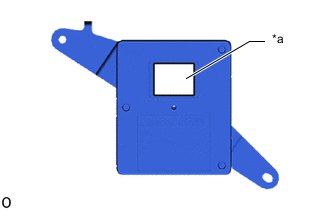
*a Black Label The type of battery voltage sensor can be confirmed by the color of the label.
-
If the wrong type of battery voltage sensor is installed, the power switch cannot be turned on (READY).
-
After installing the battery voltage sensor, perform the following to check that the power switch can be turned on (READY).
-
Turn the power switch on (READY).
-
Turn the power switch off and wait for 30 seconds or more.
-
Turn the power switch on (READY) again.
PROCEDURE
-
PRECAUTION
-
REMOVE HV BATTERY ASSEMBLY
-
REMOVE UPPER HV BATTERY COVER PANEL
-
REMOVE NO. 2 HYBRID BATTERY SHIELD SUB-ASSEMBLY
-
REMOVE NO. 1 HYBRID BATTERY SHIELD SUB-ASSEMBLY
-
REMOVE HYBRID BATTERY TERMINAL BLOCK
-
REMOVE UPPER NO. 1 HYBRID BATTERY COVER SUB-ASSEMBLY
-
REMOVE NO. 1 HYBRID BATTERY EXHAUST DUCT
-
REMOVE BATTERY VOLTAGE SENSOR (for Upper Side)
CAUTION:
-
Be sure to wear insulated gloves and protective goggles.
-
High voltage is output to the battery ECU assembly from the battery voltage sensor (for Upper Side). As a result, detach the wire harness (No. 1 HV supply stack sub-assembly) cell voltage detection circuit first.
-
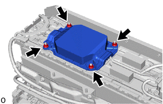
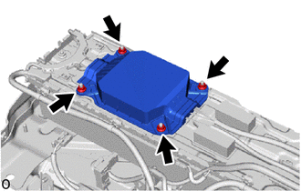
Remove the 4 nuts and No. 1 HV battery protector (for upper side).
-
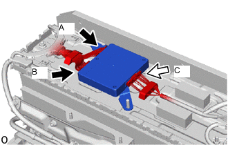
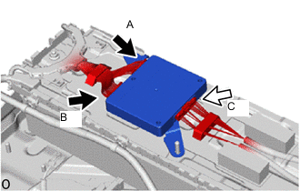
Disconnect connector A and connector B on the wire harness (No. 1 HV supply stack sub-assembly) cell voltage detection circuit.
CAUTION:
Make sure to the disconnect the connector A and connector B on the wire harness (No. 1 HV supply stack sub-assembly) cell voltage detection circuit first.
Note
Insulate each disconnected high-voltage connector with insulating tape. Wrap the connector from the wire harness side to the end of the connector
-
Disconnect connector C on the No. 1 hybrid battery pack wire side.
CAUTION:
Make sure to the disconnect the connector A and connector B on the wire harness (No. 1 HV supply stack sub-assembly) cell voltage detection circuit first.
Note
Insulate each disconnected high-voltage connector with insulating tape. Wrap the connector from the wire harness side to the end of the connector
-
Remove the battery voltage sensor (for upper side).
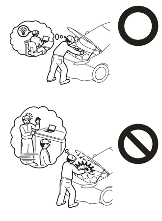
Note
-
Do not drop the battery voltage sensor (for upper side), strike it with tools or subject it to impact.
-
If the battery voltage sensor (for upper side) is subjected to an impact, replace it with a new one.
-
-
-
REMOVE BATTERY ECU ASSEMBLY
-
REMOVE NO. 7 HV BATTERY SHIELD SUB-ASSEMBLY (for Upper Side)
-
REMOVE NO. 1 HV SUPPLY STACK SUB-ASSEMBLY
-
REMOVE NO. 8 HYBRID BATTERY INTAKE DUCT
-
REMOVE WIRE HARNESS CLAMP BRACKET
-
REMOVE BATTERY COOLING BLOWER ASSEMBLY
-
REMOVE NO. 6 HYBRID BATTERY INTAKE DUCT
-
REMOVE HV BATTERY JUNCTION BLOCK ASSEMBLY
-
REMOVE UPPER HV BATTERY CARRIER SUB-ASSEMBLY
-
REMOVE BATTERY VOLTAGE SENSOR (for Lower Side)
CAUTION:
-
Be sure to wear insulated gloves and protective goggles.
-
Carry out safe work practices by disconnecting connector A and connector B on the wire harness (No. 2 HV supply stack sub-assembly) cell voltage detection circuit first.
-
Remove the 4 nuts and No. 1 HV battery protector (for lower side).
-
Disconnect connector A and connector B on the wire harness (No. 2 HV supply stack sub-assembly) cell voltage detection circuit.
CAUTION:
Make sure to the disconnect the connector A and connector B on the wire harness (No. 2 HV supply stack sub-assembly) cell voltage detection circuit first.
Note
Insulate each disconnected high-voltage connector with insulating tape. Wrap the connector from the wire harness side to the end of the connector
-
Disconnect connector C on the No. 2 hybrid battery pack wire side.
CAUTION:
Make sure to the disconnect the connector A and connector B on the wire harness (No. 2 HV supply stack sub-assembly) cell voltage detection circuit first.
Note
Insulate each disconnected high-voltage connector with insulating tape. Wrap the connector from the wire harness side to the end of the connector
-
Remove the battery voltage sensor (for lower side).
Note
-
Do not drop the battery voltage sensor (for lower side), strike it with tools or subject it to impact.
-
If the battery voltage sensor (for lower side) is subjected to an impact, replace it with a new one.
-
-