| DTC Code | DTC Name |
|---|---|
| P1BFCA2 | Battery Discharge Control Circuit System Voltage Low |
DESCRIPTION
The motor generator ECU located in the inverter with converter assembly receives power from the IGCT power source line and discharge control power source line. A semiconductor switch is installed in the motor generator ECU to switch which is used to switch the discharge control power source line power source on and off.
The motor generator ECU outputs the following DTC when it detects a discharge control power source line wiring malfunction or a semiconductor switch stuck off malfunction.
| DTC No. | Detection Item | DTC Detection Condition | Trouble Area | MIL | Warning Indicate |
|---|---|---|---|---|---|
| P1BFCA2 | Battery Discharge Control Circuit System Voltage Low | When the motor generator ECU is started, the discharge control BAT switch command flag is changed from OFF to ON after a certain period of time elapses, but the discharge control BAT voltage does not increase. (1 trip detection logic) |
|
Does not Come on | Master Warning Light: Comes on |
CONFIRMATION DRIVING PATTERN
After repair has been completed, clear the DTC and then check that the vehicle has returned to normal by performing the following All Readiness check procedure.
-
Connect the GTS to the DLC3.
-
Turn the power switch on (READY) and turn the GTS on.
-
Clear the DTCs (even if no DTCs are stored, perform the clear DTC procedure).
-
Turn the power switch off and wait for 2 minutes or more.
-
Turn the power switch on (IG) and wait for 10 seconds or more.
-
Enter the following menus: Powertrain / Hybrid Control / Utility / All Readiness.
-
Check the DTC judgment result.
Tip:
-
If the judgment result shows NORMAL, the system is normal.
-
If the judgment result shows ABNORMAL, the system has a malfunction.
-
If the judgment result shows INCOMPLETE, perform driving pattern again.
-
CAUTION / NOTICE / HINT
-

Before the following operations are conducted, take precautions to prevent electric shock by turning the power switch off, wearing insulated gloves, and removing the service plug grip from HV battery.
-
-
Inspecting the high-voltage system
-
Disconnecting the low voltage connector of the inverter with converter assembly
-
Disconnecting the low voltage connector of the HV battery
-
-
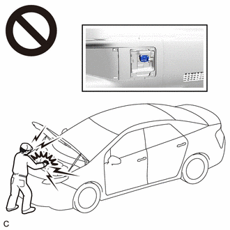
To prevent electric shock, make sure to remove the service plug grip to cut off the high voltage circuit before servicing the vehicle.
-
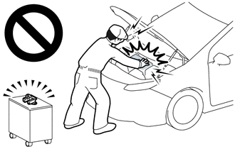
After removing the service plug grip from the HV battery, put it in your pocket to prevent other technicians from accidentally reconnecting it while you are working on the high-voltage system.
-
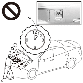
*a Without waiting for 10 minutes After removing the service plug grip, wait for at least 10 minutes before touching any of the high-voltage connectors or terminals. After waiting for 10 minutes, check the voltage at the terminals in the inspection point in the inverter with converter assembly. The voltage should be 0 V before beginning work.
Tip:Waiting for at least 10 minutes is required to discharge the high-voltage capacitor inside the inverter with converter assembly.
After turning the power switch off, waiting time may be required before disconnecting the cable from the negative (-) auxiliary battery terminal. Therefore, make sure to read the disconnecting the cable from the negative (-) auxiliary battery terminal notices before proceeding with work.
PROCEDURE
- Click here
CHECK CONNECTOR CONNECTION CONDITION (INVERTER WITH CONVERTER ASSEMBLY CONNECTOR)
CAUTION:Be sure to wear insulated gloves.
-
Check that the service plug grip is not installed.
Note:After removing the service plug grip, do not turn the power switch on (READY), unless instructed by the repair manual because this may cause a malfunction.
-
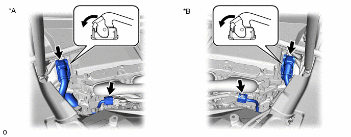
*A for LHD *B for RHD Check the connection condition of the low voltage connectors of the inverter with converter assembly and the contact pressure of each terminal. Check the terminals for deformation, and the connector for water and foreign matter.
Note:Before disconnecting the connector, confirm that it is properly connected by checking that the claws of the lock levers are engaged and that the connector cannot be pulled off.
OK - The connector is connected securely. - The terminals are not deformed and are connected securely. - No water or foreign matter in the connector. Result Result Proceed to OK A NG (The connector is not connected securely.) B NG (The terminals are not making secure contact or are deformed, or water or foreign matter exists in the connector.) C Tip:When connecting the connector, connect it with the lock levers raised. Rotate each lock lever downward and make sure that the connector is securely connected. When a lock lever is fully lowered, a click will be heard as its claw engages. After the click is heard, pull up on the connector to confirm that it is securely connected.
- AClick here
- B
CONNECT SECURELY
- C
REPAIR OR REPLACE HARNESS OR CONNECTOR
-
- Click here
CHECK HARNESS AND CONNECTOR (DISCHARGE CONTROL POWER SOURCE CIRCUIT)
CAUTION:Be sure to wear insulated gloves.
-
Check that the service plug grip is not installed.
Note:After removing the service plug grip, do not turn the power switch on (READY), unless instructed by the repair manual because this may cause a malfunction.
-
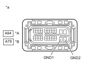
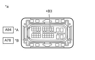
*A for LHD *B for RHD *a Front view of wire harness connector
(to Inverter with Converter Assembly)
Disconnect the A94*1, A78*2 inverter with converter assembly connector.
-
*1: for LHD
-
*2: for RHD
-
-
Measure the resistance according to the value(s) in the table below.
Standard Resistance Table 1. for LHD Tester Connection Condition Specified Condition A94-30 (GND1) - Body ground Power switch off Below 1 Ω A94-31 (GND2) - Body ground Power switch off Below 1 Ω Table 2. for RHD Tester Connection Condition Specified Condition A78-30 (GND1) - Body ground Power switch off Below 1 Ω A78-31 (GND2) - Body ground Power switch off Below 1 Ω -
Reconnect the A94*1, A78*2 inverter with converter assembly connector.
-
*1: for LHD
-
*2: for RHD
Result Proceed to OK NG -
- OKClick here
- NG
REPAIR OR REPLACE HARNESS OR CONNECTOR
-
- Click here
CHECK FUSE (MG)
-
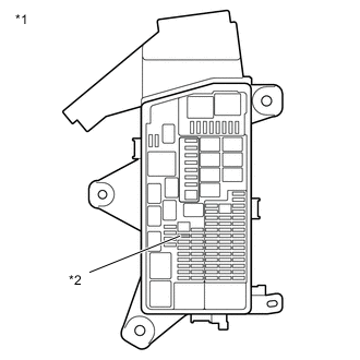
*1 No. 2 Luggage Room Relay Block Assembly *2 MG Fuse Remove the MG Fuse from the No. 2 luggage room relay block assembly.
-
Check if there is an open circuit in the MG Fuse in the No. 2 luggage room relay block assembly.
OK There is no open circuit in the MG Fuse. -
Install the MG Fuse.
Result Proceed to OK NG
- OKClick here
- NG
REPLACE FUSE (MG)
-
- Click here
CHECK HARNESS AND CONNECTOR (MG FUSE - INVERTER WITH CONVERTER ASSEMBLY)
CAUTION:Be sure to wear insulated gloves.
-
Check that the service plug grip is not installed.
Note:After removing the service plug grip, do not turn the power switch on (READY), unless instructed by the repair manual because this may cause a malfunction.
-
Remove the MG fuse from the No. 2 luggage room relay block assembly.
-
Disconnect the A94*1, A78*2 inverter with converter assembly connector.
-
*1: for LHD
-
*2: for RHD
-
-
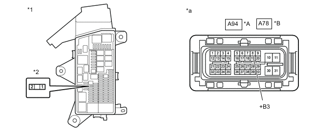
*A for LHD *B for RHD *1 No. 2 Luggage Room Relay Block Assembly *2 MG Fuse *3 Front view of wire harness connector
(to Inverter with Converter Assembly)
- - Measure the resistance according to the value(s) in the table below.
Standard Resistance Table 3. for LHD Tester Connection Condition Specified Condition 2 (MG fuse terminal) - A94-8 (+B3) Power switch off Below 1 Ω Table 4. for RHD Tester Connection Condition Specified Condition 2 (MG fuse terminal) - A78-8 (+B3) Power switch off Below 1 Ω -
Reconnect the A94*1, A78*2 inverter with converter assembly connector.
-
*1: for LHD
-
*2: for RHD
-
-
Install the MG fuse.
Result Proceed to OK NG
- OKClick here
- NG
REPAIR OR REPLACE HARNESS OR CONNECTOR
-
- Click here
CHECK HARNESS AND CONNECTOR (MG FUSE - BATTERY TERMINAL)
-
Disconnect the cable from the negative (-) auxiliary battery terminal.
-
Disconnect the cable from the positive (+) auxiliary battery terminal.
-
Remove the MG fuse from the No. 2 luggage room relay block assembly.
-
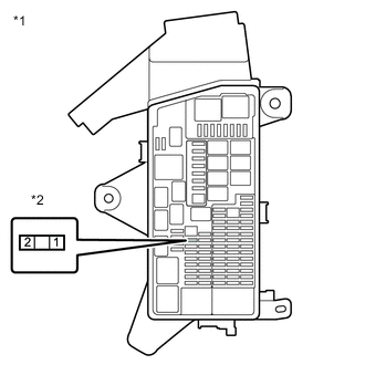
*1 No. 2 Luggage Room Relay Block Assembly *2 MG Fuse Measure the resistance according to the value(s) in the table below.
Standard Resistance Tester Connection Condition Specified Condition 1 (MG fuse terminal) - Auxiliary battery positive (+) cable Power switch off Below 1 Ω 1 (MG fuse terminal) - Body ground Power switch off 10 kΩ or higher -
Install the MG fuse.
-
Connect the cable to the positive (+) auxiliary battery terminal.
-
Connect the cable to the negative (-) auxiliary battery terminal.
Result Proceed to OK NG
- OKClick here
- NG
REPAIR OR REPLACE HARNESS OR CONNECTOR
-
- Click here
CHECK HARNESS AND CONNECTOR (DISCHARGE CONTROL POWER SOURCE CIRCUIT)
CAUTION:Be sure to wear insulated gloves.
-
Check that the service plug grip is not installed.
Note:After removing the service plug grip, do not turn the power switch on (READY), unless instructed by the repair manual because this may cause a malfunction.
-
*A for LHD *B for RHD *a Front view of wire harness connector
(to Inverter with Converter Assembly)
Disconnect the A94*1, A78*2 inverter with converter assembly connector.
-
*1: for LHD
-
*2: for RHD
-
-
Connect the cable to the negative (-) auxiliary battery terminal.
-
Measure the voltage according to the value(s) in the table below.
Standard Voltage Table 5. for LHD Tester Connection Condition Specified Condition A94-8 (+B3) - Body ground Power switch off 11 to 14 V Table 6. for RHD Tester Connection Condition Specified Condition A78-8 (+B3) - Body ground Power switch off 11 to 14 V Note:Turning the power switch on (IG) with the inverter with converter assembly connector and ECM connectors disconnected causes other DTCs to be stored. Clear the DTCs after performing this inspection.
-
Disconnect the cable from the negative (-) auxiliary battery terminal.
-
Reconnect the A94*1, A78*2 inverter with converter assembly connector.
-
*1: for LHD
-
*2: for RHD
Result Proceed to OK NG -
- OK
REPLACE INVERTER WITH CONVERTER ASSEMBLYClick here
- NG
CHECK AUXILIARY BATTERYClick here
-