HYBRID BATTERY SYSTEM, Diagnostic DTC:P0A1D94
| DTC Code | DTC Name |
|---|---|
| P0A1D94 | Hybrid/EV Powertrain Control Module Unexpected Operation |
DESCRIPTION
The battery ECU assembly monitors the hybrid vehicle control ECU assembly via CAN communication. If the battery ECU assembly detects that the hybrid vehicle control ECU assembly is malfunctioning, it will illuminate the MIL and store a DTC.
| DTC No. | Detection Item | DTC Detection Condition | Trouble Area | MIL | Warning Indicate |
|---|---|---|---|---|---|
| P0A1D94 | Hybrid/EV Powertrain Control Module Unexpected Operation | Hybrid vehicle control ECU assembly internal malfunction: An abnormal signal from the hybrid vehicle control ECU assembly is detected by the battery ECU assembly. (1 trip detection logic) |
Hybrid vehicle control ECU assembly | Comes on | Master Warning Light: Comes on |
CONFIRMATION DRIVING PATTERN
Tech Tips
After repair has been completed, clear the DTC and then check that the vehicle has returned to normal by performing the following All Readiness check procedure.
-
Connect the GTS to the DLC3.
-
Turn the power switch on (IG) and turn the GTS on.
-
Clear the DTCs (even if no DTCs are stored, perform the clear DTC procedure).
-
Turn the power switch off and wait for 2 minutes or more.
-
Turn the power switch on (IG) and turn the GTS on.
-
With power switch on (IG) and wait for 2 minutes or more.
-
Enter the following menus: Powertrain / HV Battery / Utility / All Readiness.
-
Check the DTC judgment result.
Tech Tips
-
If the judgment result shows NORMAL, the system is normal.
-
If the judgment result shows ABNORMAL, the system has a malfunction.
-
If the judgment result shows INCOMPLETE, perform driving pattern again.
-
CAUTION / NOTICE / HINT
CAUTION:
-

Before the following operations are conducted, take precautions to prevent electric shock by turning the power switch off, wearing insulated gloves, and removing the service plug grip from HV battery.
-
Inspecting the high-voltage system
-
Disconnecting the low voltage connector of the inverter with converter assembly
-
Disconnecting the low voltage connector of the HV battery
-
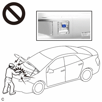
To prevent electric shock, make sure to remove the service plug grip to cut off the high voltage circuit before servicing the vehicle.
-
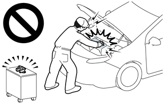
After removing the service plug grip from the HV battery, put it in your pocket to prevent other technicians from accidentally reconnecting it while you are working on the high-voltage system.
-
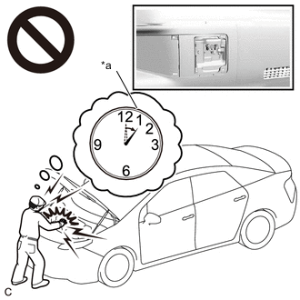
*a Without waiting for 10 minutes After removing the service plug grip, wait for at least 10 minutes before touching any of the high-voltage connectors or terminals. After waiting for 10 minutes, check the voltage at the terminals in the inspection point in the inverter with converter assembly. The voltage should be 0 V before beginning work.
Tech Tips
Waiting for at least 10 minutes is required to discharge the high-voltage capacitor inside the inverter with converter assembly and the electric vehicle charger assembly.
-
Make sure to insulate the high-voltage connectors and terminals of the HV battery with insulating tape after removing it.
If the HV battery stored without insulating the connectors and terminals, electric shock or fire may result.
Note
After turning the power switch off, waiting time may be required before disconnecting the cable from the negative (-) auxiliary battery terminal. Therefore, make sure to read the disconnecting the cable from the negative (-) auxiliary battery terminal notices before proceeding with work.
PROCEDURE
-
CHECK CONNECTOR CONNECTION CONDITION (HYBRID VEHICLE CONTROL ECU ASSEMBLY CONNECTOR)
-
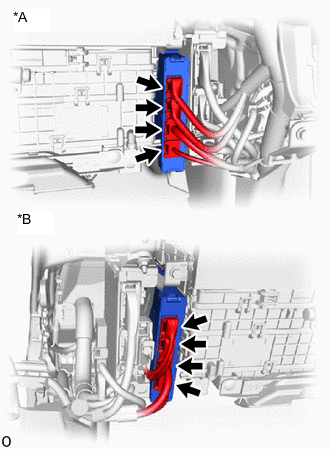
*A for LHD *B for RHD Check the connections of the hybrid vehicle control ECU connector.
OK The connector is connected securely and there are no contact problems. Result Result OK NG
NG 
CONNECT SECURELY
OK 
-
-
CHECK CONNECTOR CONNECTION CONDITION (NO. 2 HV BATTERY PACK WIRE CONNECTOR)
CAUTION:
Be sure to wear insulated gloves and protective goggles.
-
Check that the service plug grip is not installed.
Note
After removing the service plug grip, do not turn the power switch on (READY), unless instructed by the repair manual because this may cause a malfunction.
-
Remove the No. 4 hybrid battery intake duct.
-
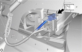
*1 Le1 Check the connector connections and contact pressure of the relevant terminals for the Le1 No. 2 HV battery pack wire connector.
OK The connectors are connected securely and there are no contact pressure problems. -
Install the No. 4 hybrid battery intake duct.
Result Proceed to OK NG
NG
CONNECT SECURELY
OK
-
-
CHECK CONNECTOR CONNECTION CONDITION (BATTERY ECU ASSEMBLY CONNECTOR)
CAUTION:
Be sure to wear insulated gloves and protective goggles.
-
Check that the service plug grip is not installed.
Note
After removing the service plug grip, do not turn the power switch on (READY), unless instructed by the repair manual because this may cause a malfunction.
-
Remove the upper No. 1 hybrid battery cover sub-assembly.
-
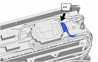
Check the connector connections and contact pressure of the relevant terminals for the e4 battery ECU assembly.
OK The connectors are connected securely and there are no contact pressure problems. -
Install the upper No. 1 hybrid battery cover sub-assembly.
Result Proceed to OK NG
NG
CONNECT SECURELY
OK
-
-
REPLACE HYBRID VEHICLE CONTROL ECU ASSEMBLY
Result Proceed to NEXT
NEXT
COMPLETED