| DTC Code | DTC Name |
|---|---|
| P0A9000 | Drive Motor "A" Performance |
DTC SUMMARY
Click here
-
MALFUNCTION DESCRIPTION
This DTC indicates that magnetic force deterioration of the permanent magnet located in the rotor inside the motor (MG2) has been detected. The cause of this malfunction may be one of the following:
Area Main Malfunction Description Inverter Inverter with converter assembly internal circuit malfunction Hybrid vehicle transmission assembly
-
Motor (MG2) malfunction (entry of foreign matter, etc.)
-
Open or short circuit in the motor coils
-
Motor (MG2) permanent magnet magnetic force deterioration
Inverter low-voltage circuit The connectors are not connected properly Motor cable
-
Defective motor cable connection condition
-
Open circuit or poor insulation in motor cable
Hybrid vehicle control ECU assembly Hybrid vehicle control ECU assembly internal circuit malfunction -
DESCRIPTION
When three-phase alternating current flows through the three-phase windings of the stator coil, a rotating magnetic field is generated in the motor (MG2). The system controls the rotation of the magnetic field in accordance with the rotating position and speed of the rotor. As a result, the permanent magnets provided in the rotor are pulled in the direction of rotation, generating torque. The generated torque is almost proportional to the amount of current. The system controls motor speed by regulating the frequency of the alternating current. Furthermore, the system properly controls the rotating magnetic field and the angle of the rotor magnets in order to generate high torque in an efficient manner, even at high speeds.
| DTC No. | Detection Item | DTC Detection Condition | Trouble Area | MIL | Warning Indicate |
|---|---|---|---|---|---|
| P0A9000 | Drive Motor "A" Performance | Motor magnetic force deterioration: Decrease in the magnetic force of the motor (MG2) is detected. (1 trip detection logic) |
|
Comes on | Master Warning Light: Comes on |
CONFIRMATION DRIVING PATTERN
After repair has been completed, clear the DTC and then check that the vehicle has returned to normal by performing the following All Readiness check procedure.
-
Connect the GTS to the DLC3.
-
Turn the power switch on (IG) and turn the GTS on.
-
Clear the DTCs (even if no DTCs are stored, perform the clear DTC procedure).
-
Turn the power switch off and wait for 2 minutes or more.
-
Turn the power switch on (IG) and turn the GTS on.
-
Turn the power switch on (READY).
-
Drive the vehicle until the cumulative traveling time driving at a vehicle speed of 40km/h (25 mph) or more is a few minutes. (It is not necessary to drive continuously at 40 km/h (25 mph) or more.)
-
Enter the following menus: Powertrain / Motor Generator / Utility / All Readiness.
-
Check the DTC judgment result.
Tip:
-
If the judgment result shows NORMAL, the system is normal.
-
If the judgment result shows ABNORMAL, the system has a malfunction.
-
If the judgment result shows INCOMPLETE, perform driving pattern again.
-
WIRING DIAGRAM
Refer to the wiring diagram for the Motor High-voltage Circuit.
Refer to the wiring diagram for the Shut Down Signal Circuit.
CAUTION / NOTICE / HINT
-

Before the following operations are conducted, take precautions to prevent electric shock by turning the power switch off, wearing insulated gloves, and removing the service plug grip from HV battery.
-
-
Inspecting the high-voltage system
-
Disconnecting the low voltage connector of the inverter with converter assembly
-
Disconnecting the low voltage connector of the HV battery
-
-
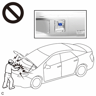
To prevent electric shock, make sure to remove the service plug grip to cut off the high voltage circuit before servicing the vehicle.
-
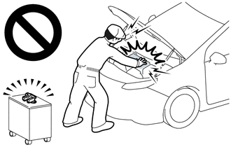
After removing the service plug grip from the HV battery, put it in your pocket to prevent other technicians from accidentally reconnecting it while you are working on the high-voltage system.
-
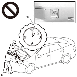
*a Without waiting for 10 minutes After removing the service plug grip, wait for at least 10 minutes before touching any of the high-voltage connectors or terminals. After waiting for 10 minutes, check the voltage at the terminals in the inspection point in the inverter with converter assembly. The voltage should be 0 V before beginning work.
Tip:Waiting for at least 10 minutes is required to discharge the high-voltage capacitor inside the inverter with converter assembly.
After turning the power switch off, waiting time may be required before disconnecting the cable from the negative (-) auxiliary battery terminal. Therefore, make sure to read the disconnecting the cable from the negative (-) auxiliary battery terminal notices before proceeding with work.
PROCEDURE
- Click here
CHECK DTC OUTPUT
-
Connect the GTS to the DLC3.
-
Turn the power switch on (IG).
-
Enter the following menus: Powertrain / Hybrid Control and Motor Generator / Trouble Codes.
-
Check for DTCs.
- Powertrain > Hybrid Control > Trouble Codes
-
-
- Powertrain > Motor Generator > Trouble Codes
-
-
Result Result Proceed to P0A9000 only is output, or DTCs except the ones in the table below are also output. A DTCs of hybrid control system in the tables below are output. B DTCs of motor generator control system in the tables below are output. C Table 1. Table 1 Malfunction Content System Relevant DTC Insulation Malfunction Hybrid control system P1C7C49 Hybrid/EV Battery Voltage System Isolation (A/C Area) Internal Electronic Failure P1C7D49 Hybrid/EV Battery Voltage System Isolation (Hybrid/EV Battery Area) Internal Electronic Failure P1C7E49 Hybrid/EV Battery Voltage System Isolation (Transaxle Area) Internal Electronic Failure P1C7F49 Hybrid/EV Battery Voltage System Isolation (Direct Current Area) Internal Electronic Failure System Main Relay or High Voltage Circuit Malfunction Hybrid control system P0AD911 Hybrid/EV Battery Positive Contactor Circuit Short to Ground P0AD915 Hybrid/EV Battery Positive Contactor Circuit Short to Auxiliary Battery or Open P0ADD11 Hybrid/EV Battery Negative Contactor Circuit Short to Ground P0ADD15 Hybrid/EV Battery Negative Contactor Circuit Short to Auxiliary Battery or Open P1C8449 High Voltage Power Resource Circuit Short during Ready ON Table 2. Table 2 Malfunction Content System Relevant DTC Microcomputer malfunction Motor generator control system P0A1A47 Generator Control Module Watchdog / Safety μC Failure P0A1A49 Generator Control Module Internal Electronic Failure P0A1B1F Generator Control Module Circuit Intermittent P1C2A1C Generator A/D Converter Circuit Circuit Voltage Out of Range P1C2A49 Generator A/D Converter Circuit Internal Electronic Failure P1C2B1C Drive Motor "A" Control Module A/D Converter Circuit Voltage Out of Range P1C2B49 Drive Motor "A" Control Module A/D Converter Circuit Internal Electronic Failure P313383 Communication Error from Generator to Drive Motor "A" Value of Signal Protection Calculation Incorrect P313386 Communication Error from Generator to Drive Motor "A" Signal Invalid P313387 Communication Error from Generator to Drive Motor "A" Missing Message P313483 Communication Error from Drive Motor "A" to Generator Value of Signal Protection Calculation Incorrect P313486 Communication Error from Drive Motor "A" to Generator Signal Invalid P313487 Communication Error from Drive Motor "A" to Generator Missing Message Hybrid control system P0A1B49 Drive Motor "A" Control Module Internal Electronic Failure Power source circuit malfunction Motor generator control system P06B01C Generator Control Module Position Sensor REF Power Source Circuit Voltage Out of Range P06D61C Generator Control Module Offset Power Circuit Voltage Out of Range Sensor and actuator circuit malfunction Motor generator control system P0A3F16 Drive Motor "A" Position Sensor Circuit Voltage Below Threshold P0A3F21 Drive Motor "A" Position Sensor Signal Amplitude < Minimum P0A3F22 Drive Motor "A" Position Sensor Signal Amplitude > Maximum P0A4B16 Generator Position Sensor Circuit Voltage Below Threshold P0A4B21 Generator Position Sensor Signal Amplitude < Minimum P0A4B22 Generator Position Sensor Signal Amplitude > Maximum P0A6012 Drive Motor "A" Phase V Current (High Resolution) Circuit Short to Battery P0A6014 Drive Motor "A" Phase V Current (High Resolution) Circuit Short to Ground or Open P0A601C Drive Motor "A" Phase V Current (High Resolution) Circuit Voltage Out of Range P0A6312 Drive Motor "A" Phase W Current (High Resolution) Circuit Short to Battery P0A6314 Drive Motor "A" Phase W Current (High Resolution) Circuit Short to Ground or Open P0A631C Drive Motor "A" Phase W Current (High Resolution) Circuit Voltage Out of Range P0BE912 Drive Motor "A" Phase V Current Sensor Circuit Short to Battery P0BE914 Drive Motor "A" Phase V Current Sensor Circuit Short to Ground or Open P0BE928 Drive Motor "A" Phase V Current Sensor Signal Bias Level Out of Range / Zero Adjustment Failure P0BED12 Drive Motor "A" Phase W Current Sensor Circuit Short to Battery P0BED14 Drive Motor "A" Phase W Current Sensor Circuit Short to Ground or Open P0BED28 Drive Motor "A" Phase W Current Sensor Signal Bias Level Out of Range / Zero Adjustment Failure P0C5013 Drive Motor "A" Position Sensor Circuit "A" Circuit Open P0C5016 Drive Motor "A" Position Sensor Circuit "A" Circuit Voltage Below Threshold P0C5017 Drive Motor "A" Position Sensor Circuit "A" Circuit Voltage Above Threshold P0C5A13 Drive Motor "A" Position Sensor Circuit "B" Circuit Open P0C5A16 Drive Motor "A" Position Sensor Circuit "B" Circuit Voltage Below Threshold P0C5A17 Drive Motor "A" Position Sensor Circuit "B" Circuit Voltage Above Threshold P0C6413 Generator Position Sensor Circuit "A" Circuit Open P0C6416 Generator Position Sensor Circuit "A" Circuit Voltage Below Threshold P0C6417 Generator Position Sensor Circuit "A" Circuit Voltage Above Threshold P0C6913 Generator Position Sensor Circuit "B" Circuit Open P0C6916 Generator Position Sensor Circuit "B" Circuit Voltage Below Threshold P0C6917 Generator Position Sensor Circuit "B" Circuit Voltage Above Threshold P0D2D16 Drive Motor "A" Inverter Voltage Sensor (VH) Circuit Voltage Below Threshold P0D2D17 Drive Motor "A" Inverter Voltage Sensor (VH) Circuit Voltage Above Threshold P0E0412 Generator Phase V Current Sensor Circuit Short to Battery P0E0414 Generator Phase V Current Sensor Circuit Short to Ground or Open P0E0428 Generator Phase V Current Sensor Signal Bias Level Out of Range / Zero Adjustment Failure P0E0812 Generator Phase W Current Sensor Circuit Short to Battery P0E0814 Generator Phase W Current Sensor Circuit Short to Ground or Open P0E0828 Generator Phase W Current Sensor Signal Bias Level Out of Range / Zero Adjustment Failure P0E3116 DC/DC Converter Voltage Sensor "A" (VL) Circuit Voltage Below Threshold P0E3117 DC/DC Converter Voltage Sensor "A" (VL) Circuit Voltage Above Threshold P1C3C62 Drive Motor "A" Phase V Current Sensor Correlation Signal Compare Failure P1C4928 Drive Motor "A" Phase V Current Sensor "B" Signal Bias Level Out of Range / Zero Adjustment Failure P1C4914 Drive Motor "A" Phase V Current Sensor "B" Circuit Short to Ground or Open P1C4912 Drive Motor "A" Phase V Current Sensor "B" Circuit Short to Battery P1C3D62 Drive Motor "A" Phase W Current Sensor Correlation Signal Compare Failure P1C4E14 Drive Motor "A" Phase W Current Sensor "B" Circuit Short to Ground or Open P1C4E12 Drive Motor "A" Phase W Current Sensor "B" Circuit Short to Battery P1C4E28 Drive Motor "A" Phase W Current Sensor "B" Signal Bias Level Out of Range / Zero Adjustment Failure P1C3E62 Generator Phase V Current Sensor Correlation Signal Compare Failure P1C5328 Generator Phase V Current Sensor "B" Signal Bias Level Out of Range / Zero Adjustment Failure P1C5314 Generator Phase V Current Sensor "B" Circuit Short to Ground or Open P1C5312 Generator Phase V Current Sensor "B" Circuit Short to Battery P1C3F62 Generator Phase W Current Sensor Correlation Signal Compare Failure P1C5828 Generator Phase W Current Sensor "B" Signal Bias Level Out of Range / Zero Adjustment Failure P1C5814 Generator Phase W Current Sensor "B" Circuit Short to Ground or Open P1C5812 Generator Phase W Current Sensor "B" Circuit Short to Battery P1CAC49 Generator Position Sensor Internal Electronic Failure P1CAD49 Drive Motor "A" Position Sensor Internal Electronic Failure P1CAF38 Generator Position Sensor REF Signal Cycle Malfunction Signal Frequency Incorrect P1CB038 Drive Motor "A" Position Sensor REF Signal Frequency Incorrect Hybrid control system P0C7600 Hybrid/EV Battery System Discharge Time Too Long P0D2D1C Drive Motor "A" Inverter Voltage Sensor Voltage Out of Range P0E311C Boosting Converter Voltage Sensor "A" Voltage Out of Range P1C2D62 Hybrid/EV Battery "A" Voltage Sensor/Boosting Converter Voltage Sensor "A" Signal Compare Failure System malfunction Motor generator control system P0A7873 Drive Motor "A" Inverter Actuator Stuck Closed P0A7A73 Generator Inverter Actuator Stuck Closed P0C1900 Drive Motor "A" Execution Torque Performance P0E7100 Generator Execution Torque Performance Tip:
-
P0A9000 may be output as a result of the malfunction indicated by the DTCs above.
-
-
The chart above is listed in inspection order of priority.
-
Check DTCs that are output at the same time by following the listed order. (The main cause of the malfunction can be determined without performing unnecessary inspections.)
-
-
Turn the power switch off.
- AClick here
- B
GO TO DTC CHART (HYBRID CONTROL SYSTEM)Click here
- C
GO TO DTC CHART (MOTOR GENERATOR CONTROL SYSTEM)Click here
-
- Click here
CHECK FREEZE FRAME DATA AND DIAGNOSIS RELATED INFORMATION
-
Connect the GTS to the DLC3.
-
Turn the power switch on (IG).
-
Enter the following menus: Powertrain / Hybrid Control / Utility / Diagnosis Related Information.
- Powertrain > Hybrid Control > Utility
Tester Display Diagnosis Related Information -
-
-
-
- Powertrain > Hybrid Control > Utility
-
Enter the following menus: Powertrain / Motor Generator / Trouble Codes.
- Powertrain > Motor Generator > Trouble Codes
-
-
-
Read the diagnosis related information and freeze frame data of DTC P0A9000.
Result Result Proceed to DTC P312387 is listed in Diagnosis Related Information. A DTC P312387 is not listed in Diagnosis Related Information and the value of freeze frame data item Emergency Shutdown Signal is ON. B Other than above C -
Turn the power switch off.
- A
GO TO DTC CHART (P312387)Click here
- B
GO TO DTC CHART (P321E9F)Click here
- CClick here
-
- Click here
SIMULATION TEST
-
Connect the GTS to the DLC3.
-
Clear the DTCs.
- Powertrain > Motor Generator > Clear DTCs
-
-
-
Turn the power switch on (READY).
-
Push the P position switch.
-
Turn the air conditioning system on and wait for 1 minute with the engine stopped.
Tip:If the engine starts before 1 minute has elapsed, wait until it stops and then perform this step again.
-
Enter the following menus: Powertrain / Motor Generator / Trouble Codes.
-
Check for DTCs.
- Powertrain > Motor Generator > Trouble Codes
-
-
Result Result Proceed to P0A9000 or P0BFF1D is output, or DTC is not output. A DTCs other than P0A9000 and P0BFF1D is also output. B -
Turn the power switch off.
- AClick here
- B
GO TO DTC CHART (MOTOR GENERATOR CONTROL SYSTEM)Click here
-
- Click here
SIMULATION TEST
-
Connect the GTS to the DLC3.
-
Clear the DTCs.
- Powertrain > Motor Generator > Clear DTCs
-
-
-
Turn the power switch on (READY).
-
Select drive (D).
-
Depress the accelerator pedal half way or more and accelerate the vehicle to 20 km/h (12.4 mph).
CAUTION:When performing the confirmation driving pattern, obey all speed limits and traffic laws.
-
Enter the following menus: Powertrain / Motor Generator / Trouble Codes.
-
Check for DTCs.
- Powertrain > Motor Generator > Trouble Codes
-
-
Result Result Proceed to P0A9000 or P0BFF1D is output, or DTC is not output. A DTCs other than P0A9000 and P0BFF1D is also output. B -
Turn the power switch off.
- AClick here
- B
GO TO DTC CHART (MOTOR GENERATOR CONTROL SYSTEM)Click here
-
- Click here
CHECK CONNECTOR CONNECTION CONDITION (INVERTER WITH CONVERTER ASSEMBLY CONNECTOR)
Result Result Proceed to OK A NG (The connector is not connected securely.) B NG (The terminals are not making secure contact or are deformed, or water or foreign matter exists in the connector.) C CAUTION:Be sure to wear insulated gloves.
-
Check that the service plug grip is not installed.
Note:After removing the service plug grip, do not turn the power switch on (READY), unless instructed by the repair manual because this may cause a malfunction.
-
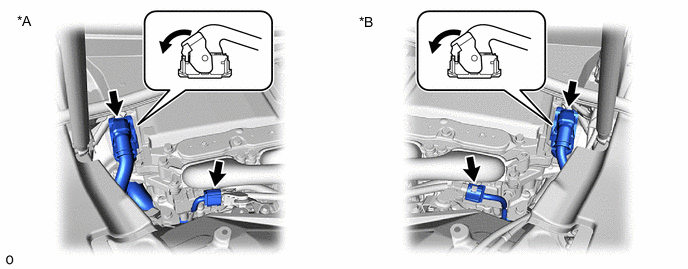
*A for LHD *B for RHD Check the connection condition of the low voltage connectors of the inverter with converter assembly and the contact pressure of each terminal. Check the terminals for deformation, and the connector for water and foreign matter.
Note:Before disconnecting the connector, confirm that it is properly connected by checking that the claws of the lock levers are engaged and that the connector cannot be pulled off.
OK - The connector is connected securely. - The terminals are not deformed and are connected securely. - No water or foreign matter in the connector. Result Result Proceed to OK A NG (The connector is not connected securely.) B NG (The terminals are not making secure contact or are deformed, or water or foreign matter exists in the connector.) C Tip:When connecting the connector, connect it with the lock levers raised. Rotate each lock lever downward and make sure that the connector is securely connected. When a lock lever is fully lowered, a click will be heard as its claw engages. After the click is heard, pull up on the connector to confirm that it is securely connected.
- AClick here
- B
CONNECT SECURELY
- C
REPAIR OR REPLACE HARNESS OR CONNECTOR
-
- Click here
CHECK SHUT DOWN SIGNAL CIRCUIT
Result Proceed to NEXT
- NEXTClick here
- Click here
CHECK MOTOR HIGH-VOLTAGE CIRCUIT
Tip:If the "Motor High-voltage Circuit" inspection results are normal, perform the next step.
Result Proceed to NEXT
- NEXT
REPLACE HYBRID VEHICLE TRANSMISSION ASSEMBLY for 2WD:
REPLACE HYBRID VEHICLE TRANSMISSION ASSEMBLYClick here
REPLACE HYBRID VEHICLE TRANSMISSION ASSEMBLY for AWD:
REPLACE HYBRID VEHICLE TRANSMISSION ASSEMBLYClick here
- NEXT