Click here
-
DESCRIPTION
-
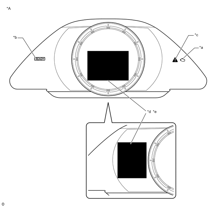
*A for F-SPORT Meter - - *a MIL *b READY Light *c Master Warning Light *d Charge Warning *e Multi-information Display - - 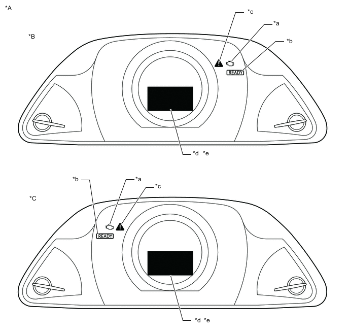
*A except Sport Package *B for LHD *B for RHD - - *a MIL *b READY Light *c Master Warning Light *d Charge Warning *e Multi-information Display - - The motor generator control ECU (MG ECU) (inverter with converter assembly) has a self-diagnosis system. If the motor generator control ECU (MG ECU), motor generator system or a component is not working properly, the ECU records the conditions that relate to the fault. The ECU also illuminates the master warning light in the combination meter assembly and provides other appropriate messages on the multi-information display, such as the HV system warning message, HV battery warning message or discharge warning message.
Tip:The master warning light will illuminate if the motor generator control system is malfunctioning and will blink when in inspection mode.
-
-
2 TRIP DETECTION LOGIC
- Following is the description for storage of DTC using "2 trip detection logic".
-
When a malfunction is first detected, the malfunction is temporarily stored in the motor generator control ECU memory (1st trip). If the same malfunction is detected during the next drive cycle, the MIL is illuminated (2nd trip).
-
FREEZE FRAME DATA
-
The motor generator control ECU records vehicle and driving condition information as freeze frame data the moment a DTC is stored. When troubleshooting, freeze frame data can be helpful in determining whether the vehicle was moving or stationary, whether the engine was warmed up or not, as well as other data recorded at the time of a malfunction.
-
-
AUXILIARY BATTERY VOLTAGE
Standard Voltage Switch Condition Specified Condition Power switch on (IG) 11 to 14 V
-
If voltage is below 11 V, recharge or replace the auxiliary battery.
Note:After turning the power switch off, waiting time may be required before disconnecting the cable from the negative (-) auxiliary battery terminal. Therefore, make sure to read the disconnecting the cable from the negative (-) auxiliary battery terminal notices before proceeding with work.
-
-
MIL (Malfunction Indicator Lamp)
-
The MIL is illuminated when the power switch is first turned on (IG), before the READY indicator illuminates.
-
When the READY indicator illuminates, the MIL should turn off. If the MIL remains illuminated, the diagnosis system has detected a malfunction or abnormality in a system.
Tip:If the MIL is not illuminated when the power switch is first turned on (IG), check the MIL circuit.
w/ Canister Pump Module:
w/o Canister Pump Module:
-
-
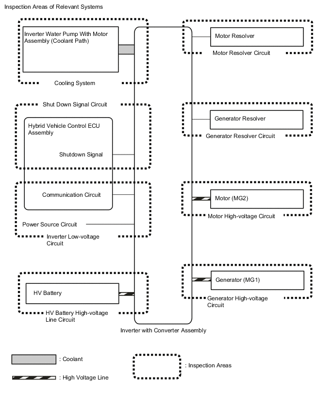
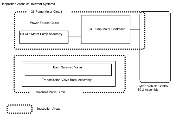
RELEVANT SYSTEMS CHECK
The inspection areas and outline of the inspection for each circuit are listed below.
Table 1. Inspection Details of Relevant Systems System to be Inspected Malfunction Possibility Inspection Content Oil Pump Motor Circuit Oil pump motor lock
-
Open or short in signal line between hybrid vehicle control ECU assembly, oil pump motor controller and oil pump with motor assembly
-
Oil pump motor controller power source circuit
-
Short to +B in oil pump with motor assembly
Solenoid Valve Circuit Solenoid valve inside transmission valve body stuck
-
Check each solenoid valve
-
Check transmission valve body assembly
(no abnormality or foreign matter in solenoid installation area)
Table 2. Inspection Details of Relevant Systems System to be Inspected Malfunction Possibility Inspection Content Motor Resolver Circuit Motor resolver signal
-
Open or short circuit in the motor resolver, connectors or cables
Motor High-voltage Circuit Motor (MG2) output
-
Open or short circuit in the motor (MG2), connectors or cables
Generator Resolver Circuit Generator resolver signal
-
Open or short circuit in the generator resolver, connectors or cables
Generator High-voltage Circuit Generator (MG1) output
-
Open or short circuit in the generator (MG1), connectors or cables
Inverter Low-voltage Circuit Power supply voltage from +B or communication between hybrid vehicle control ECU assembly and motor generator control ECU
-
Open or short circuit in communication line between hybrid vehicle control ECU assembly and motor generator control ECU
-
Open or short circuit in the +B or ground lines
-
Fuse is blown
HV Battery High-voltage Line Circuit High voltage power supply from HV battery
-
Open or short circuit in the system main relay, connectors or cables
Cooling System Temperature abnormally high
-
Grille blockage
-
Whether coolant is present
-
Whether there is a possibility that coolant was frozen when malfunction occurs
-
Cooling hose blockage
-
HV radiator fan operation
Shutdown Signal System Shutdown signal
-
Open or short circuit in shutdown signal communication line between hybrid vehicle control ECU assembly and motor generator ECU
-
-
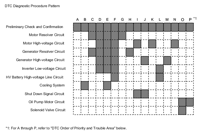
DTC PRIORITY LEVEL AND TROUBLE AREAS
-
Each DTC diagnostic procedure for the hybrid control system consists of a combination of the various relevant system (circuit) inspections.
-
When multiple DTCs are output, performing each diagnostic procedure in order of priority can lead to a more accurate diagnosis.
Table 3. Inspection Details of Relevant Systems DTC No. Detection Item Order of Priority Inspection Pattern 1 2 3 4 5 Microcomputer Malfunction Power Source Circuit Malfunction Communication System Malfunction Sensor and Actuator Circuit Malfunction System Malfunction P033500 Crankshaft Position Sensor "A" - - - ○ - - P033531 Crankshaft Position Sensor "A" No Signal - - - ○ - - P034000 Camshaft Position Sensor "A" Circuit Bank 1 or Single Sensor - - - ○ - - P034031 Camshaft Position Sensor "A" Circuit Bank 1 or Single Sensor No Signal - - - ○ - - P062F44 Internal Control Module EEPROM Data Memory Failure ○ - - - - - P062F46 Generator Control Module (EEPROM Learning Value) Calibration / Parameter Memory Failure ○ - - - - - P06B01C Generator Control Module Position Sensor REF Power Source Circuit Voltage Out of Range - ○ - - - - P06D61C Generator Control Module Offset Power Circuit Voltage Out of Range - ○ - - - - P0A0011 Motor Electronics Coolant Temperature Sensor Circuit Short to Ground - - - ○ - - P0A0015 Motor Electronics Coolant Temperature Sensor Circuit Short to Battery or Open - - - ○ - - P0A001C Motor Electronics Coolant Temperature Sensor Circuit Voltage Out of Range - - - ○ - B P0A1A47 Generator Control Module Watchdog / Safety μC Failure ○ - - - - - P0A1A49 Generator Control Module Internal Electronic Failure ○ - - - - - P0A1B1F Generator Control Module Circuit Intermittent ○ - - - - - P0A3F16 Drive Motor "A" Position Sensor Circuit Voltage Below Threshold - - - ○ - G P0A3F1F Drive Motor "A" Position Sensor Circuit Intermittent - - - ○ - G P0A3F21 Drive Motor "A" Position Sensor Signal Amplitude < Minimum - - - ○ - G P0A3F22 Drive Motor "A" Position Sensor Signal Amplitude > Maximum - - - ○ - G P0A4B16 Generator Position Sensor Circuit Voltage Below Threshold - - - ○ - H P0A4B1F Generator Position Sensor Circuit Intermittent - - - ○ - H P0A4B21 Generator Position Sensor Signal Amplitude < Minimum - - - ○ - H P0A4B22 Generator Position Sensor Signal Amplitude > Maximum - - - ○ - H P0A6012 Drive Motor "A" Phase V Current (High Resolution) Circuit Short to Battery - - - ○ - A P0A6014 Drive Motor "A" Phase V Current (High Resolution) Circuit Short to Ground or Open - - - ○ - A P0A601C Drive Motor "A" Phase V Current (High Resolution) Circuit Voltage Out of Range - - - ○ - A P0A601F Drive Motor "A" Phase V Current (High Resolution) Circuit Intermittent - - - ○ - A P0A6312 Drive Motor "A" Phase W Current (High Resolution) Circuit Short to Battery - - - ○ - A P0A6314 Drive Motor "A" Phase W Current (High Resolution) Circuit Short to Ground or Open - - - ○ - A P0A631C Drive Motor "A" Phase W Current (High Resolution) Circuit Voltage Out of Range - - - ○ - A P0A631F Drive Motor "A" Phase W Current (High Resolution) Circuit Intermittent - - - ○ - A P0A7872 Drive Motor "A" Inverter Actuator Stuck Open - - - - ○ A P0A7873 Drive Motor "A" Inverter Actuator Stuck Closed - - - - ○ - P0A789E Drive Motor "A" Inverter Stuck On - - - - ○ E P0A7A72 Generator Inverter Actuator Stuck Open - - - - ○ A P0A7A73 Generator Inverter Actuator Stuck Closed - - - - ○ - P0A7A9E Generator Inverter Stuck On - - - - ○ E P0A9000 Drive Motor "A" Performance - - - - ○ I P0A9200 Hybrid Generator Performance - - - - ○ J P0A949E DC/DC Converter Stuck On - - - - ○ E P0AED11 Drive Motor Inverter Temperature Sensor "A" Circuit Short to Ground - - - ○ - - P0AED15 Drive Motor Inverter Temperature Sensor "A" Circuit Short to Battery or Open - - - ○ - - P0AED1C Drive Motor Inverter Temperature Sensor "A" Circuit Voltage Out of Range - - - ○ - B P0AED46 Drive Motor Inverter Temperature Sensor "A" Calibration / Parameter Memory Failure ○ - - - - - P0BCC11 Generator Inverter Temperature Sensor Circuit Short to Ground - - - ○ - - P0BCC15 Generator Inverter Temperature Sensor Circuit Short to Battery or Open - - - ○ - - P0BCC1C Generator Inverter Temperature Sensor Circuit Voltage Out of Range - - - ○ - B P0BCC46 Generator Inverter Temperature Sensor Calibration / Parameter Memory Failure ○ - - - - - P0BE912 Drive Motor "A" Phase V Current Sensor Circuit Short to Battery - - - ○ - A P0BE914 Drive Motor "A" Phase V Current Sensor Circuit Short to Ground or Open - - - ○ - A P0BE91F Drive Motor "A" Phase V Current Sensor Circuit Intermittent - - - ○ - A P0BE928 Drive Motor "A" Phase V Current Sensor Signal Bias Level Out of Range / Zero Adjustment Failure - - - ○ - A P0BED12 Drive Motor "A" Phase W Current Sensor Circuit Short to Battery - - - ○ - A P0BED14 Drive Motor "A" Phase W Current Sensor Circuit Short to Ground or Open - - - ○ - A P0BED1F Drive Motor "A" Phase W Current Sensor Circuit Intermittent - - - ○ - A P0BED28 Drive Motor "A" Phase W Current Sensor Signal Bias Level Out of Range / Zero Adjustment Failure - - - ○ - A P0BFF1D Drive Motor "A" Circuit Current Out of Range - - - - ○ I P0C1900 Drive Motor "A" Execution Torque Performance - - - - ○ I P0C3811 DC/DC Converter Temperature Sensor "A" Circuit Short to Ground - - - ○ - - P0C3815 DC/DC Converter Temperature Sensor "A" Circuit Short to Battery or Open - - - ○ - - P0C381C DC/DC Converter Temperature Sensor "A" Circuit Voltage Out of Range - - - ○ - B P0C3846 DC/DC Converter Temperature Sensor "A" Calibration / Parameter Memory Failure ○ - - - - - P0C3D11 DC/DC Converter Temperature Sensor "B" Circuit Short to Ground - - - ○ - - P0C3D15 DC/DC Converter Temperature Sensor "B" Circuit Short to Battery or Open - - - ○ - - P0C3D1C DC/DC Converter Temperature Sensor "B" Circuit Voltage Out of Range - - - ○ - B P0C3D46 DC/DC Converter Temperature Sensor "B" Calibration / Parameter Memory Failure ○ - - - - - P0C5013 Drive Motor "A" Position Sensor Circuit "A" Circuit Open - - - ○ - G P0C5016 Drive Motor "A" Position Sensor Circuit "A" Circuit Voltage Below Threshold - - - ○ - A P0C5017 Drive Motor "A" Position Sensor Circuit "A" Circuit Voltage Above Threshold - - - ○ - A P0C501F Drive Motor "A" Position Sensor Circuit "A" Circuit Intermittent - - - ○ - A P0C5A13 Drive Motor "A" Position Sensor Circuit "B" Circuit Open - - - ○ - G P0C5A16 Drive Motor "A" Position Sensor Circuit "B" Circuit Voltage Below Threshold - - - ○ - A P0C5A17 Drive Motor "A" Position Sensor Circuit "B" Circuit Voltage Above Threshold - - - ○ - A P0C5A1F Drive Motor "A" Position Sensor Circuit "B" Circuit Intermittent - - - ○ - A P0C6413 Generator Position Sensor Circuit "A" Circuit Open - - - ○ - H P0C6416 Generator Position Sensor Circuit "A" Circuit Voltage Below Threshold - - - ○ - A P0C6417 Generator Position Sensor Circuit "A" Circuit Voltage Above Threshold - - - ○ - A P0C641F Generator Position Sensor Circuit "A" Circuit Intermittent - - - ○ - C P0C6913 Generator Position Sensor Circuit "B" Circuit Open - - - ○ - H P0C6916 Generator Position Sensor Circuit "B" Circuit Voltage Below Threshold - - - ○ - A P0C6917 Generator Position Sensor Circuit "B" Circuit Voltage Above Threshold - - - ○ - A P0C691F Generator Position Sensor Circuit "B" Circuit Intermittent - - - ○ - A P0C7917 Drive Motor "A" Inverter Voltage Sensor (VH) Circuit Voltage Above Threshold - - - - ○ F P0CA300 DC/DC Converter Step Up Voltage Performance - - - - ○ A P0D2D16 Drive Motor "A" Inverter Voltage Sensor (VH) Circuit Voltage Below Threshold - - - ○ - - P0D2D17 Drive Motor "A" Inverter Voltage Sensor (VH) Circuit Voltage Above Threshold - - - ○ - - P0D2D1F Drive Motor "A" Inverter Voltage Sensor (VH) Circuit Intermittent - - - ○ - - P0D3319 DC/DC Converter Circuit Current Above Threshold - - - - ○ E P0E0412 Generator Phase V Current Sensor Circuit Short to Battery - - - ○ - A P0E0414 Generator Phase V Current Sensor Circuit Short to Ground or Open - - - ○ - A P0E041F Generator Phase V Current Sensor Circuit Intermittent - - - ○ - A P0E0428 Generator Phase V Current Sensor Signal Bias Level Out of Range / Zero Adjustment Failure - - - ○ - A P0E0812 Generator Phase W Current Sensor Circuit Short to Battery - - - ○ - A P0E0814 Generator Phase W Current Sensor Circuit Short to Ground or Open - - - ○ - A P0E081F Generator Phase W Current Sensor Circuit Intermittent - - - ○ - A P0E0828 Generator Phase W Current Sensor Signal Bias Level Out of Range / Zero Adjustment Failure - - - ○ - A P0E3116 DC/DC Converter Voltage Sensor "A" (VL) Circuit Voltage Below Threshold - - - ○ - - P0E3117 DC/DC Converter Voltage Sensor "A" (VL) Circuit Voltage Above Threshold - - - ○ - - P0E311F DC/DC Converter Voltage Sensor "A" (VL) Circuit Intermittent - - - ○ - - P0E5717 DC/DC Converter Voltage Sensor "A" (VL) Circuit Voltage Above Threshold - - - - ○ F P0E7100 Generator Execution Torque Performance - - - - ○ J P160600 Collision detected or Collision Sensor Connection (Open) - - - - - - P160604 Collision detected or Collision Sensor Connection (Open) System Internal Failure - - - - - - P1BFB9E Battery Discharge Control Circuit Stuck On - ○ - - - A P1BFCA2 Battery Discharge Control Circuit System Voltage Low - ○ - - - A P1C2A1C Generator A/D Converter Circuit Circuit Voltage Out of Range ○ - - - - H P1C2A49 Generator A/D Converter Circuit Internal Electronic Failure ○ - - - - A P1C2B1C Drive Motor "A" Control Module A/D Converter Circuit Voltage Out of Range ○ - - - - I P1C2B49 Drive Motor "A" Control Module A/D Converter Circuit Internal Electronic Failure ○ - - - - A P1C2E46 Motor Generator ECU (EEPROM) Calibration / Parameter Memory Failure ○ - - - - - P1C3C1F Drive Motor "A" Phase V Current Sensor Correlation Circuit Intermittent - - - ○ - M P1C3C62 Drive Motor "A" Phase V Current Sensor Correlation Signal Compare Failure - - - ○ - N P1C3D1F Drive Motor "A" Phase W Current Sensor Correlation Circuit Intermittent - - - ○ - M P1C3D62 Drive Motor "A" Phase W Current Sensor Correlation Signal Compare Failure - - - ○ - N P1C3E1F Generator Phase V Current Sensor Correlation Circuit Intermittent - - - ○ - N P1C3E62 Generator Phase V Current Sensor Correlation Signal Compare Failure - - - ○ - M P1C3F1F Generator Phase W Current Sensor Correlation Circuit Intermittent - - - ○ - N P1C3F62 Generator Phase W Current Sensor Correlation Signal Compare Failure - - - ○ - M P1C4912 Drive Motor "A" Phase V Current Sensor "B" Circuit Short to Battery - - - ○ - A P1C4914 Drive Motor "A" Phase V Current Sensor "B" Circuit Short to Ground or Open - - - ○ - A P1C491F Drive Motor "A" Phase V Current Sensor "B" Circuit Intermittent - - - ○ - A P1C4928 Drive Motor "A" Phase V Current Sensor "B" Signal Bias Level Out of Range / Zero Adjustment Failure - - - ○ - A P1C4E12 Drive Motor "A" Phase W Current Sensor "B" Circuit Short to Battery - - - ○ - A P1C4E14 Drive Motor "A" Phase W Current Sensor "B" Circuit Short to Ground or Open - - - ○ - A P1C4E1F Drive Motor "A" Phase W Current Sensor "B" Circuit Intermittent - - - ○ - A P1C4E28 Drive Motor "A" Phase W Current Sensor "B" Signal Bias Level Out of Range / Zero Adjustment Failure - - - ○ - A P1C5312 Generator Phase V Current Sensor "B" Circuit Short to Battery - - - ○ - A P1C5314 Generator Phase V Current Sensor "B" Circuit Short to Ground or Open - - - ○ - A P1C531F Generator Phase V Current Sensor "B" Circuit Intermittent - - - ○ - A P1C5328 Generator Phase V Current Sensor "B" Signal Bias Level Out of Range / Zero Adjustment Failure - - - ○ - A P1C5812 Generator Phase W Current Sensor "B" Circuit Short to Battery - - - ○ - A P1C5814 Generator Phase W Current Sensor "B" Circuit Short to Ground or Open - - - ○ - A P1C581F Generator Phase W Current Sensor "B" Circuit Intermittent - - - ○ - A P1C5828 Generator Phase W Current Sensor "B" Signal Bias Level Out of Range / Zero Adjustment Failure - - - ○ - A P1C5D19 Drive Motor "A" Inverter Circuit Current Above Threshold - - - - ○ E P1C5F19 Generator Inverter Circuit Current Above Threshold - - - - ○ E P1C601F Generator Control Module Position Sensor REF Power Source Circuit Intermittent - ○ - - - A P1C621F Generator Control Module Offset Power Circuit Intermittent - ○ - - - D P1C641F Generator Control Module Circuit Intermittent ○ - - - - D P1C651F Generator Control Module Circuit Intermittent ○ - - - - - P1CA51D Hybrid Generator Circuit Current Out of Range - - - - ○ J P1CAC49 Generator Position Sensor Internal Electronic Failure - - - ○ - C P1CAD49 Drive Motor "A" Position Sensor Internal Electronic Failure - - - ○ - C P1CAF38 Generator Position Sensor REF Signal Cycle Malfunction Signal Frequency Incorrect - - - ○ - C P1CB038 Drive Motor "A" Position Sensor REF Signal Frequency Incorrect - - - ○ - C P1CB59E DC/DC Converter Voltage Sensor "A" (VL) Stuck On - - - - ○ A P1CB69E Drive Motor "A" Inverter Voltage Sensor (VH) Stuck On - - - - ○ A P31241F Lost Communication between Drive Motor "A" and HV ECU Circuit Intermittent - - ○ - - - P312487 Lost Communication between Drive Motor "A" and HV ECU Missing Message - - ○ - - - P313383 Communication Error from Generator to Drive Motor "A" Value of Signal Protection Calculation Incorrect ○ - - - - - P313386 Communication Error from Generator to Drive Motor "A" Signal Invalid ○ - - - - - P313387 Communication Error from Generator to Drive Motor "A" Missing Message ○ - - - - - P313483 Communication Error from Drive Motor "A" to Generator Value of Signal Protection Calculation Incorrect ○ - - - - - P313486 Communication Error from Drive Motor "A" to Generator Signal Invalid ○ - - - - - P313487 Communication Error from Drive Motor "A" to Generator Missing Message ○ - - - - - P314F1F DC/DC Converter Voltage Sensor "A" (VL) Circuit Intermittent - - - - ○ F P322F11 Communication Error from Airbag to Generator Circuit Short to Ground - - ○ - - - P322F15 Communication Error from Airbag to Generator Circuit Short to Battery or Open - - ○ - - - P322F64 Communication Error from Airbag to Generator Signal Plausibility Failure - - ○ - - - U010087 Lost Communication With ECM/PCM "A" Missing Message - - ○ - - - U029387 Lost Communication With Hybrid Powertrain Control Module Missing Message - - ○ - - - U117087 Lost Communication With Brake System Control Module(ch2) Missing Message - - ○ - - - Tip:The "Example of Multiple DTCs being Output" below is only one example of a malfunction condition. Therefore, a determination should not be made based on this alone.
- Example of Multiple DTCs being Output:
-
The power supply of the microcomputer decreases while the vehicle is being driven.
-
-
DTCs are detected and the vehicle behavior is as follows.
-
-
- Detected DTCs
-
P06B01C (Generator Control Module Position Sensor REF Power Source Circuit Voltage Out of Range): Power source circuit malfunction*
-
P0C5016 (Drive Motor "A" Position Sensor Circuit "A" Circuit Voltage Below Threshold): Sensor and actuator circuit malfunction*
-
P0A3F16 (Drive Motor "A" Position Sensor Circuit Voltage Below Threshold): Sensor and actuator circuit malfunction*
-
P1CAD49 (Drive Motor "A" Position Sensor Internal Electronic Failure): Sensor and actuator circuit malfunction*
-
P1CAC49 (Generator Position Sensor Internal Electronic Failure): Sensor and actuator circuit malfunction*
-
-
*: Check the priority level in the "DTC Order of Priority" chart above.
-
-
- Vehicle Behavior
-
System stopped
-
The inspection order of priority is: Microcomputer circuit → power source circuit → communication circuit → sensor and actuator circuit → system circuit. Therefore, check the repair procedure for P0B601C.
-
Follow the repair procedures and replace the inverter assembly. Finish the repair.
It is possible to check only the specified malfunctioning parts without having to check irrelevant parts.
-