HYBRID CONTROL SYSTEM, Diagnostic DTC:P0AA749
| DTC Code | DTC Name |
|---|---|
| P0AA749 | Hybrid/EV Battery Voltage Isolation Sensor Circuit Internal Electronic Failure |
DESCRIPTION
The hybrid vehicle control ECU assembly monitors the insulation monitoring circuit located in the battery ECU assembly and detects malfunctions.
| DTC No. | Detection Item | DTC Detection Condition | Trouble Area | MIL | Warning Indicate |
|---|---|---|---|---|---|
| P0AA749 | Hybrid/EV Battery Voltage Isolation Sensor Circuit Internal Electronic Failure | Malfunction in the insulation monitoring circuit in the battery ECU assembly (1 trip detection logic) |
|
Does not come on | Master Warning Light: Comes on |
| DTC No. | Data List |
|---|---|
| P0AA749 | Short Wave Highest Value Level |
CONFIRMATION DRIVING PATTERN
Tech Tips
After repairs have been completed, clear the DTCs and then check that the vehicle has returned to normal by performing the following All Readiness check procedure.
-
Connect the GTS to the DLC3.
-
Turn the power switch on (IG) and turn the GTS on.
-
Clear the DTCs (even if no DTCs are stored, perform the clear DTC procedure).
-
Turn the power switch off and wait for 2 minutes or more.
-
Turn the power switch on (IG) and turn the GTS on.
-
With power switch on (IG) and wait for 70 seconds or more.
-
Enter the following menus: Powertrain / Hybrid Control / Utility / All Readiness.
-
Check the DTC judgment result.
Tech Tips
-
If the judgment result shows NORMAL, the system is normal.
-
If the judgment result shows ABNORMAL, the system has a malfunction.
-
If the judgment result shows INCOMPLETE, perform driving pattern again.
-
CAUTION / NOTICE / HINT
CAUTION:
-

Before the following operations are conducted, take precautions to prevent electric shock by turning the power switch off, wearing insulated gloves, and removing the service plug grip from HV battery.
-
Inspecting the high-voltage system
-
Disconnecting the low voltage connector of the inverter with converter assembly
-
Disconnecting the low voltage connector of the HV battery
-
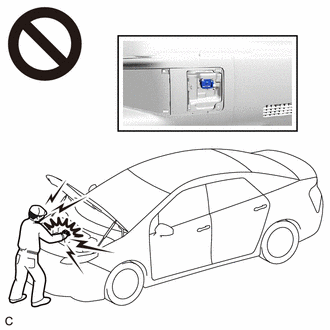
To prevent electric shock, make sure to remove the service plug grip to cut off the high voltage circuit before servicing the vehicle.
-
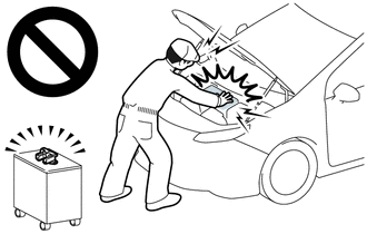
After removing the service plug grip from the HV battery, put it in your pocket to prevent other technicians from accidentally reconnecting it while you are working on the high-voltage system.
-
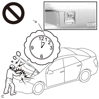
*a Without waiting for 10 minutes After removing the service plug grip, wait for at least 10 minutes before touching any of the high-voltage connectors or terminals. After waiting for 10 minutes, check the voltage at the terminals in the inspection point in the inverter with converter assembly. The voltage should be 0 V before beginning work.
Tech Tips
Waiting for at least 10 minutes is required to discharge the high-voltage capacitor inside the inverter with converter assembly.
-
Make sure to insulate the high-voltage connectors and terminals of the HV battery with insulating tape after removing it.
If the HV battery stored without insulating the connectors and terminals, electric shock or fire may result.
-
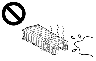
After removing the HV battery or the HV supply stack sub-assembly, keep it away from water. Exposure to water may cause the HV battery or the HV supply stack sub-assembly to produce heat, resulting in a fire.
Note
After turning the power switch off, waiting time may be required before disconnecting the cable from the negative (-) auxiliary battery terminal. Therefore, make sure to read the disconnecting the cable from the negative (-) auxiliary battery terminal notices before proceeding with work.
PROCEDURE
-
CLEAR DTC
Result Proceed to NEXT
-
Connect the GTS to the DLC3.
-
Turn the power switch on (IG).
-
Enter the following menus: Powertrain / Hybrid Control / Trouble Codes.
-
Read and record the DTCs and freeze frame data.
Powertrain > Hybrid Control > Trouble Codes -
Clear the DTCs and freeze frame data.
Powertrain > Hybrid Control > Clear DTCs -
Turn the power switch off.
Result Proceed to NEXT
NEXT 
-
-
SIMULATION TEST
-
Connect the GTS to the DLC3.
-
Turn the power switch on (IG) and wait for 70 seconds or more.
Note
Do not turn the power switch off until step 3 is complete.
-
Enter the following menus: Powertrain / Hybrid Control / Trouble Codes.
-
Check if DTCs are output.
Powertrain > Hybrid Control > Trouble CodesResult Proceed to P0AA749 is not output. P0AA749 is output.
P0AA749 is output. 
REPLACE BATTERY ECU ASSEMBLY Click here
P0AA749 is not output.
-
-
SIMULATION TEST
Note
Do not turn the power switch off while performing this inspection.
-
With the vehicle and engine stopped, turn the power switch on (READY) with park (P) selected and wait for 70 seconds or more. (If the engine starts, wait until the engine stops.)
-
While depressing the brake pedal without depressing the accelerator pedal, move the shift lever to select shift state drive (D) and wait for 1 minute. (Step A)
-
Drive the vehicle 0.5 m (1.6 ft.) forward and perform step A.
-
Drive the vehicle another 0.5 m (1.6 ft.) forward and perform step A. Repeat this procedure 5 times (minimum total driving distance: 2 m (6.6 ft.)).
-
Enter the following menus: Powertrain / Hybrid Control / Trouble Codes.
-
Check if DTCs are output.
Powertrain > Hybrid Control > Trouble CodesResult Proceed to P0AA649 is not output. P0AA649 is output. -
Turn the power switch off.
P0AA649 is output.
GO TO DTC CHART (P0AA649) Click here
P0AA649 is not output.
-
-
CHECK HARNESS AND CONNECTOR (BATTERY ECU ASSEMBLY - BATTERY VOLTAGE SENSOR (for Upper Side))
Result Proceed to OK NG CAUTION:
Be sure to wear insulated gloves and protective goggles.
-
Check that the service plug grip is not installed.
Note
After removing the service plug grip, do not turn the power switch on (READY), unless instructed by the repair manual because this may cause a malfunction.
-
Remove the No. 1 HV battery protector (for upper side).
-
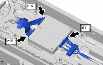
Disconnect the d1 battery voltage sensor (for upper side) connector.
CAUTION:
Before disconnecting the d1 battery voltage sensor (for Upper Side) connector, disconnect the z14 and z15 connectors.
-
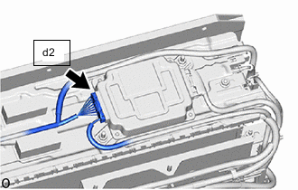
Disconnect the d2 battery ECU assembly connector.
Note
-
Insulate each disconnected high-voltage connector with insulating tape. Wrap the connector from the wire harness side to the end of the connector.
-
Before disconnecting the connector, check that it is not loose or disconnected.
-
-
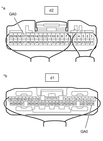
*a Rear view of wire harness and connector
(to Battery ECU Assembly)
*b Rear view of wire harness and connector
(to Battery Voltage Sensor (for Upper Side))
Measure the resistance according to the value(s) in the table below.
Standard Resistance Tester Connection Condition Specified Condition d2-17 (GA0) - d1-19 (GA0) Power switch off Below 1 Ω d2-17 (GA0) or d1-19 (GA0) - Body ground and other terminals Power switch off 10 kΩ or higher -
Reconnect the d2 battery ECU assembly connector.
-
Reconnect the d1 battery voltage sensor (for upper side) connector.
CAUTION:
Before connecting the z14 and z15 battery voltage sensor (for Upper Side) connectors, connect the d1 connector.
Result Proceed to OK NG
NG
REPAIR OR REPLACE HARNESS OR CONNECTOR
OK
-
-
INSPECT BATTERY VOLTAGE SENSOR (for Upper Side)
Result Proceed to OK NG CAUTION:
Be sure to wear insulated gloves and protective goggles.
Note
When checking the battery voltage sensor (for Upper Side) resistance, select a probe of appropriate thickness (approximately 0.5 mm) from the tester lead set, and perform the measurement.
-
Disconnect the d1 battery voltage sensor (for upper side) connector.
CAUTION:
Before disconnecting the d1 battery voltage sensor (for Upper Side) connector, disconnect the z14 and z15 connectors.
-
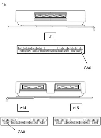
*a Component without harness connected
(Battery Voltage Sensor (for Upper Side))
Measure the resistance according to the value(s) in the table below.
Standard Resistance Tester Connection Condition Specified Condition d1-19 (GA0) - z14-10 (GA0) Power switch off 5.88 to 6.12 kΩ d1-19 (GA0) or z14-10 (GA0) - Body ground and other terminals Power switch off 10 kΩ or higher -
Reconnect the d1 battery voltage sensor (for upper side) connector.
CAUTION:
Before connecting the z14 and z15 battery voltage sensor (for Upper Side) connectors, connect the d1 connector.
Result Proceed to OK NG
OK
REPLACE BATTERY ECU ASSEMBLY Click here
NG
REPLACE BATTERY VOLTAGE SENSOR (for Upper Side) Click here
-