| DTC Code | DTC Name |
|---|---|
| P0AA073 | Hybrid/EV Battery Positive and Negative Contactor Actuator Stuck Closed |
DTC SUMMARY
Click here
-
MALFUNCTION DESCRIPTION
The hybrid vehicle control ECU assembly detects a stuck closed malfunction of a system main relay on the positive (+) terminal side and negative (-) terminal side of the HV battery.
The cause of this malfunction may be one of the following:
- Inverter voltage sensor (VH) internal circuit malfunction
-
Voltage sensor (VH) malfunction
-
Motor generator control ECU (MG ECU) malfunction
-
Communication (wire harness) malfunction
- High voltage system malfunction
-
HV battery junction block assembly malfunction
- Low-voltage circuit (12 V) malfunction
-
Hybrid vehicle control ECU assembly malfunction
-
HV battery junction block assembly malfunction
-
Low voltage wire harness malfunction
-
Low voltage connector malfunction
DESCRIPTION
Refer to the description for DTC P0AE411.
This circuit uses the hybrid vehicle control ECU assembly to monitor the system main relays and stops the system if a malfunction is detected in the relays, because it may be impossible to shut off the high-voltage system if any of the relays becomes stuck.
| DTC No. | Detection Item | DTC Detection Condition | Trouble Area | MIL | Warning Indicate |
|---|---|---|---|---|---|
| P0AA073 | Hybrid/EV Battery Positive and Negative Contactor Actuator Stuck Closed | Even both of the system main relays (HV battery positive (+) and negative (-) terminal side) are turned off, the inverter voltage (VH) does not drop. (1 trip detection logic) |
|
Does not come on | Master Warning Light: Comes on |
| DTC No. | Data List |
|---|---|
| P0AA073 |
|
CONFIRMATION DRIVING PATTERN
After repairs have been completed, clear the DTCs and then check that the vehicle has returned to normal by performing the following All Readiness check procedure.
-
Connect the GTS to the DLC3.
-
Turn the power switch on (IG) and turn the GTS on.
-
Clear the DTCs (even if no DTCs are stored, perform the clear DTC procedure).
-
Turn the power switch off and wait for 2 minutes or more.
-
Turn the power switch on (IG) and turn the GTS on.
-
Turn the power switch on (READY) and wait for 2 minutes or more.
Tip:According to the display on the GTS, read the Data List and monitor the values of "Hybrid Battery Voltage" and "VL-Voltage before Boosting" for 3 minutes. If the difference between "Hybrid Battery Voltage" and "VL-Voltage before Boosting" is always less than 100 V, the vehicle has returned to normal.
-
Enter the following menus: Powertrain / Hybrid Control / Utility / All Readiness.
-
Check the DTC judgment result.
Tip:
-
If the judgment result shows NORMAL, the system is normal.
-
If the judgment result shows ABNORMAL, the system has a malfunction.
-
If the judgment result shows INCOMPLETE, perform driving pattern again.
-
CAUTION / NOTICE / HINT
-

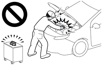
Before the following operations are conducted, take precautions to prevent electric shock by turning the power switch off, wearing insulated gloves, and removing the service plug grip from HV battery.
-
-
Inspecting the high-voltage system
-
Disconnecting the low voltage connector of the inverter with converter assembly
-
Disconnecting the low voltage connector of the HV battery
-
-
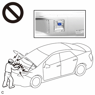
To prevent electric shock, make sure to remove the service plug grip to cut off the high voltage circuit before servicing the vehicle.
-
After removing the service plug grip from the HV battery, put it in your pocket to prevent other technicians from accidentally reconnecting it while you are working on the high-voltage system.
-
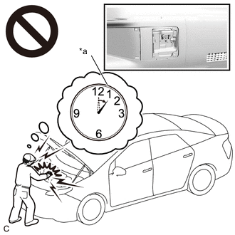
*a Without waiting for 10 minutes After removing the service plug grip, wait for at least 10 minutes before touching any of the high-voltage connectors or terminals. After waiting for 10 minutes, check the voltage at the terminals in the inspection point in the inverter with converter assembly. The voltage should be 0 V before beginning work.
Tip:Waiting for at least 10 minutes is required to discharge the high-voltage capacitor inside the inverter with converter assembly.
-
Make sure to insulate the high-voltage connectors and terminals of the HV battery with insulating tape after removing it.
If the HV battery stored without insulating the connectors and terminals, electric shock or fire may result.
-
After turning the power switch off, waiting time may be required before disconnecting the cable from the negative (-) auxiliary battery terminal. Therefore, make sure to read the disconnecting the cable from the negative (-) auxiliary battery terminal notices before proceeding with work.
-
If the DTCs are cleared or the cable is disconnected and reconnected to the negative (-) auxiliary battery terminal before performing repairs, turning the power switch on (READY) may cause a malfunction. Do not turn the power switch on (READY).
-
Do not turn the power switch on (IG) with the service plug grip removed, as this may cause a malfunction.
-
If DTC P0AA073 is output, do not install the service plug grip before completing repair.
If the service plug grip is not removed, the HV battery will gradually discharge and the SOC will decrease.
If DTC P0AA073 is output, the power switch cannot be turned on (READY).
PROCEDURE
- Click here
CHECK DTC OUTPUT (HYBRID CONTROL, MOTOR GENERATOR)
-
Connect the GTS to the DLC3.
-
Turn the power switch on (IG).
-
Enter the following menus: Powertrain / Hybrid Control and Motor Generator / Trouble Codes.
-
Check for DTCs.
- Powertrain > Hybrid Control > Trouble Codes
-
-
- Powertrain > Motor Generator > Trouble Codes
-
-
Result Result Proceed to P0AA073 only is output, or DTCs except the ones in the table below are also output. A DTCs of hybrid control system in the tables below are output. B DTCs of motor generator control system in the tables below are output. C Malfunction Content System Relevant DTC Microcomputer malfunction Hybrid control system P060647 Hybrid/EV Powertrain Control Module Processor Watchdog / Safety MCU Failure P060687 Hybrid/EV Powertrain Control Module Processor to Monitoring Processor Missing Message P060A47 Hybrid/EV Powertrain Control Module Monitoring Processor Watchdog / Safety MCU Failure P060A87 Hybrid/EV Powertrain Control Module Processor from Monitoring Processor Missing Message P0A1B49 Drive Motor "A" Control Module Internal Electronic Failure P1C9E9F Hybrid/EV System Reset Stuck Off Motor generator control system P0A1B1F Generator Control Module Circuit Intermittent P0A1A47 Generator Control Module Watchdog / Safety μC Failure P0A1A49 Generator Control Module Internal Electronic Failure P1C2A1C Generator A/D Converter Circuit Circuit Voltage Out of Range P1C2A49 Generator A/D Converter Circuit Internal Electronic Failure P1C2B1C Drive Motor "A" Control Module A/D Converter Circuit Voltage Out of Range P1C2B49 Drive Motor "A" Control Module A/D Converter Circuit Internal Electronic Failure P1CAC49 Generator Position Sensor Internal Electronic Failure P1CAD49 Drive Motor "A" Position Sensor Internal Electronic Failure P1CAF38 Generator Position Sensor REF Signal Cycle Malfunction Signal Frequency Incorrect P1CB038 Drive Motor "A" Position Sensor REF Signal Frequency Incorrect P313383 Communication Error from Generator to Drive Motor "A" Value of Signal Protection Calculation Incorrect P313386 Communication Error from Generator to Drive Motor "A" Signal Invalid P313387 Communication Error from Generator to Drive Motor "A" Missing Message Power source circuit malfunction Motor generator control system P06D61C Generator Control Module Offset Power Circuit Voltage Out of Range P06B01C Generator Control Module Position Sensor REF Power Source Circuit Voltage Out of Range Communication system malfunction Hybrid control system P312387 Lost Communication with Drive Motor Control Module "A" from Hybrid/EV Control Module Missing Message Sensor and actuator circuit malfunction Hybrid control system P0AD911 Hybrid/EV Battery Positive Contactor Circuit Short to Ground P0AD915 Hybrid/EV Battery Positive Contactor Circuit Short to Auxiliary Battery or Open P0ADD11 Hybrid/EV Battery Negative Contactor Circuit Short to Ground P0ADD15 Hybrid/EV Battery Negative Contactor Circuit Short to Auxiliary Battery or Open P0AE411 Hybrid/EV Battery Precharge Contactor Circuit Short to Ground P0AE415 Hybrid/EV Battery Precharge Contactor Circuit Short to Auxiliary Battery or Open Motor generator control system P0A3F16 Drive Motor "A" Position Sensor Circuit Voltage Below Threshold P0A4B16 Generator Position Sensor Circuit Voltage Below Threshold P0A4B21 Generator Position Sensor Signal Amplitude < Minimum P0A4B22 Generator Position Sensor Signal Amplitude > Maximum P0C5013 Drive Motor "A" Position Sensor Circuit "A" Circuit Open P0C5016 Drive Motor "A" Position Sensor Circuit "A" Circuit Voltage Below Threshold P0C5017 Drive Motor "A" Position Sensor Circuit "A" Circuit Voltage Above Threshold P0C5A13 Drive Motor "A" Position Sensor Circuit "B" Circuit Open P0C5A16 Drive Motor "A" Position Sensor Circuit "B" Circuit Voltage Below Threshold P0C5A17 Drive Motor "A" Position Sensor Circuit "B" Circuit Voltage Above Threshold P0C6413 Generator Position Sensor Circuit "A" Circuit Open P0C6416 Generator Position Sensor Circuit "A" Circuit Voltage Below Threshold P0C6417 Generator Position Sensor Circuit "A" Circuit Voltage Above Threshold P0C6913 Generator Position Sensor Circuit "B" Circuit Open P0C6916 Generator Position Sensor Circuit "B" Circuit Voltage Below Threshold P0C6917 Generator Position Sensor Circuit "B" Circuit Voltage Above Threshold System malfunction Hybrid control system P0C7600 Hybrid/EV Battery System Discharge Time Too Long P0D2D1C Drive Motor "A" Inverter Voltage Sensor Voltage Out of Range P1C8349 High Voltage Power Resource Circuit Voltage Sensor after Boosting Malfunction Motor generator control system P0D2D16 Drive Motor "A" Inverter Voltage Sensor (VH) Circuit Voltage Below Threshold P0D2D17 Drive Motor "A" Inverter Voltage Sensor (VH) Circuit Voltage Above Threshold P1CB69E Drive Motor "A" Inverter Voltage Sensor (VH) Stuck On Tip:
-
P0AA073 may be output as a result of the malfunction indicated by the DTCs above.
-
-
The chart above is listed in inspection order of priority.
-
Check DTCs that are output at the same time by following the listed order. (The main cause of the malfunction can be determined without performing unnecessary inspections.)
-
-
Turn the power switch off.
- AClick here
- B
GO TO DTC CHART (HYBRID CONTROL SYSTEM)Click here
- C
GO TO DTC CHART (MOTOR GENERATOR CONTROL SYSTEM)Click here
-
- Click here
CHECK FREEZE FRAME DATA (HYBRID CONTROL)
-
Connect the GTS to the DLC3.
-
Turn the power switch on (IG).
-
Enter the following menus: Powertrain / Hybrid Control / Trouble Codes.
-
Read the freeze frame data of DTC P0AA073.
- Powertrain > Hybrid Control > Trouble Codes
-
-
Note:As freeze frame data is stored immediately before and after a DTC is stored, make sure to only read the values for the moment the DTC was stored ("0(s)").
Result Result Proceed to Difference between "VL-Voltage before Boosting" and "VH-Voltage after Boosting" is less than 41 V. A Difference between "VL-Voltage before Boosting" and "VH-Voltage after Boosting" is 41 V or more. B Tip:If VH-Voltage after Boosting is output even when an off command is being sent to the system main relay (positive side), P0AA073 is output. If the difference between the "VL-Voltage before Boosting" and the "VH-Voltage after Boosting" is large, it is determined that there is an inverter (VH sensor) malfunction.
-
Turn the power switch off.
- AClick here
- B
REPLACE INVERTER WITH CONVERTER ASSEMBLYClick here
-
- Click here
CHECK CONNECTOR CONNECTION CONDITION (HYBRID VEHICLE CONTROL ECU ASSEMBLY CONNECTOR)
Result Proceed to OK NG
-
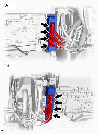
*A for LHD *B for RHD Check the connector connections and contact pressure of the relevant terminals for the hybrid vehicle control ECU assembly connectors.
OK The connectors are connected securely and there are no contact pressure problems. Result Proceed to OK NG
- OKClick here
GO TO STEP 5
- NGClick here
-
- Click here
CONNECT SECURELY
Result Proceed to NEXT
- NEXTClick here
- Click here
CHECK CONNECTOR CONNECTION CONDITION (FLOOR WIRE CONNECTOR)
Result Result Proceed to OK A NG (The connector is not connected securely.) B NG (The terminals are not making secure contact or are deformed, or water or foreign matter exists in the connector.) C
-
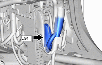
Check the connection condition of the LG1 floor wire connector and the contact pressure of each terminal. Check the terminals for deformation, and check the connector for water ingress and foreign matter.
OK - The connector is connected securely. - The terminals are not deformed and are connected securely. - No water or foreign matter in the connector. Result Result Proceed to OK A NG (The connector is not connected securely.) B NG (The terminals are not making secure contact or are deformed, or water or foreign matter exists in the connector.) C
- AClick here
GO TO STEP 8
- BClick here
- CClick here
-
- Click here
CONNECT SECURELY
Result Proceed to NEXT
- NEXTClick here
GO TO STEP 8
- NEXTClick here
- Click here
REPAIR OR REPLACE HARNESS OR CONNECTOR
Result Proceed to NEXT
- NEXTClick here
- Click here
CHECK CONNECTOR CONNECTION CONDITION (HV BATTERY JUNCTION BLOCK ASSEMBLY CONNECTOR)
Result Proceed to OK NG CAUTION:Be sure to wear insulated gloves.
-
Check that the service plug grip is not installed.
Note:After removing the service plug grip, do not turn the power switch on (READY), unless instructed by the repair manual because this may cause a malfunction.
-
Remove the No. 10 HV battery shield panel.
-
Check the connector connections and contact pressure of the relevant terminals of the HV battery junction block assembly connector.
OK The connectors are connected securely and there are no contact pressure problems. -
Install the No. 10 HV battery shield panel.
Result Proceed to OK NG
- OKClick here
GO TO STEP 10
- NGClick here
-
- Click here
CONNECT SECURELY
Result Proceed to NEXT
- NEXTClick here
- Click here
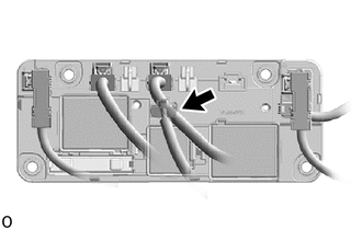
CHECK GROUND WIRE CONNECTION CONDITION (SMR ACTIVATION LOW-VOLTAGE CIRCUIT)
Result Proceed to OK NG
-
Check the installation condition of the ground wire LG.
OK The ground wire LG is securely installed. Result Proceed to OK NG
- OKClick here
GO TO STEP 12
- NGClick here
-
- Click here
CONNECT SECURELY
Result Proceed to NEXT
- NEXTClick here
- Click here
CHECK HARNESS AND CONNECTOR (HYBRID VEHICLE CONTROL ECU ASSEMBLY - HV BATTERY JUNCTION BLOCK ASSEMBLY)
CAUTION:Be sure to wear insulated gloves.
-
Check that the service plug grip is not installed.
Note:After removing the service plug grip, do not turn the power switch on (IG), unless instructed by the repair manual because this may cause a malfunction.
-
Remove the No. 10 HV battery shield panel.
-
Disconnect the e2 HV battery junction block assembly connector.
-
Disconnect the G92 hybrid vehicle control ECU assembly connector.
-
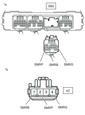
*a Rear view of wire harness connector
(to Hybrid Vehicle Control ECU Assembly)
*b Front view of wire harness connector
(to HV Battery Junction Block Assembly)
Measure the resistance according to the value(s) in the table below.
Standard Resistance (Check for Open) Tester Connection Condition Specified Condition G92-5 (SMRB) - e2-1 (SMRB) Power switch off Below 1 Ω G92-1 (SMRG) - e2-4 (SMRG) Power switch off Below 1 Ω G92-15 (SMRP) - e2-2 (SMRP) Power switch off Below 1 Ω Standard Resistance (Check for Short) Tester Connection Condition Specified Condition G92-5 (SMRB) or e2-1 (SMRB) - Body ground and other terminals Power switch off 10 kΩ or higher G92-1 (SMRG) or e2-4 (SMRG) - Body ground and other terminals Power switch off 10 kΩ or higher G92-15 (SMRP) or e2-2 (SMRP) - Body ground and other terminals Power switch off 10 kΩ or higher -
Reconnect the G92 hybrid vehicle control ECU assembly connector.
-
Reconnect the e2 HV battery junction block assembly connector.
-
Install the No. 10 HV battery shield panel.
Result Proceed to OK NG
- OKClick here
GO TO STEP 14
- NGClick here
-
- Click here
REPAIR OR REPLACE HARNESS OR CONNECTOR
Result Proceed to NEXT
- NEXTClick here
- Click here
CHECK HARNESS AND CONNECTOR (HV BATTERY JUNCTION BLOCK ASSEMBLY - BODY GROUND)
CAUTION:Be sure to wear insulated gloves.
-
Check that the service plug grip is not installed.
Note:After removing the service plug grip, do not turn the power switch on (IG), unless instructed by the repair manual because this may cause a malfunction.
-
Remove the No. 10 HV battery shield panel.
-
Disconnect the e2 HV battery junction block assembly connector.
-
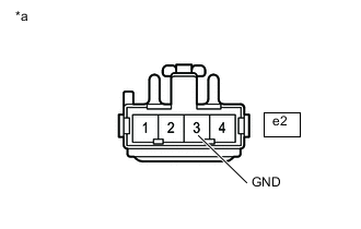
*a Front view of wire harness connector
(to HV Battery Junction Block Assembly)
Measure the resistance according to the value(s) in the table below.
Standard Resistance Tester Connection Condition Specified Condition e2-3 (GND) - Body ground Power switch off Below 1 Ω -
Reconnect the e2 HV battery junction block assembly connector.
-
Install the No. 10 HV battery shield panel.
Result Proceed to OK NG
- OKClick here
GO TO STEP 16
- NGClick here
-
- Click here
REPAIR OR REPLACE HARNESS OR CONNECTOR
Result Proceed to NEXT
- NEXTClick here
- Click here
INSPECT HV BATTERY JUNCTION BLOCK ASSEMBLY (SMRB, SMRG, SMRP)
CAUTION:Be sure to wear insulated gloves.
-
Check that the service plug grip is not installed.
Note:After removing the service plug grip, do not turn the power switch on (IG), unless instructed by the repair manual because this may cause a malfunction.
-
Remove the No. 10 HV battery shield panel.
-
Disconnect the e2 HV battery junction block assembly connector.
-
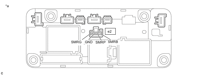
*a Component without harness connected
(HV Battery Junction Block Assembly)
- - Measure the resistance according to the value(s) in the table below.
Standard Resistance Tester Connection Condition Specified Condition e2-1 (SMRB) - e2-3 (GND) -40 to 80°C (-40 to 176°F) 25.0 to 59.0 Ω e2-4 (SMRG) - e2-3 (GND) -40 to 80°C (-40 to 176°F) 25.0 to 59.0 Ω e2-2 (SMRP) - e2-3 (GND) -40 to 80°C (-40 to 176°F) 140 to 290 Ω -
Reconnect the e2 HV battery junction block assembly connector.
-
Install the No. 10 HV battery shield panel.
Result Proceed to OK NG
- OKClick here
- NGClick here
-
- Click here
CHECK HV BATTERY JUNCTION BLOCK ASSEMBLY (SMRB, SMRG, SMRP)
CAUTION:Be sure to wear insulated gloves.
-
Check that the service plug grip is not installed.
Note:After removing the service plug grip, do not turn the power switch on (IG), unless instructed by the repair manual because this may cause a malfunction.
-
Remove the No. 10 HV battery shield panel.
-
Disconnect the 2 HV floor under wire connectors from the HV battery junction block assembly.
Note:Insulate each disconnected high-voltage connector with insulating tape. Wrap the connector from the wire harness side to the end of the connector.
-
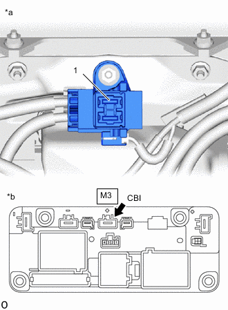
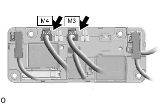
*a Service Plug Grip Removed
(Service Plug Grip Connecting Terminals)
*b Component without harness connected
(HV Battery Junction Block Assembly)
Measure the resistance according to the value(s) in the table below.
Standard Resistance (SMRB) Tester Connection Condition Specified Condition 1 - M3-1 (CBI) Power switch off 10 kΩ or higher Tip:
-
If a system main relay is stuck closed, inspect the HV battery junction block assembly without removing it from the vehicle, in order to keep the relay closed.
-
If the result of reading the freeze frame data is A, the HV battery junction block assembly must be replaced. Measuring resistance can determine that this is either a present or past malfunction.
-
-
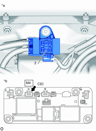
*a Service Plug Grip Removed
(Service Plug Grip Connecting Terminals)
*b Component without harness connected
(HV Battery Junction Block Assembly)
Measure the resistance according to the value(s) in the table below.
Standard Resistance (SMRG, SMRP) Tester Connection Condition Specified Condition 2 - M4-1 (CEI) Power switch off 10 kΩ or higher Tip:
-
If a system main relay is stuck closed, inspect the HV battery junction block assembly without removing it from the vehicle, in order to keep the relay closed.
-
If the result of reading the freeze frame data is A, the HV battery junction block assembly must be replaced. Measuring resistance can determine that this is either a present or past malfunction.
-
If the resistance is between 24.3 and 29.7 Ω, it can be determined that SMRP is stuck closed.
-
-
Reconnect the 2 HV floor under wire connectors.
-
Install the No. 10 HV battery shield panel.
Result Result Judgment Proceed to OK Past malfunction A NG Present malfunction B
-
- Click here
REPLACE HV BATTERY JUNCTION BLOCK ASSEMBLY
Result Proceed to NEXT
- NEXTClick here
GO TO STEP 21
- NEXTClick here
- Click here
REPLACE HV BATTERY JUNCTION BLOCK ASSEMBLY
Result Proceed to NEXT
- NEXTClick here
GO TO STEP 21
- NEXTClick here
- Click here
REPLACE HV BATTERY JUNCTION BLOCK ASSEMBLY
Result Proceed to NEXT
- NEXTClick here
- Click here
CHECK HYBRID VEHICLE CONTROL ECU ASSEMBLY (CHECK FOR NORMAL OPERATION)
Result Result Proceed to Difference between "Hybrid Battery Voltage" and "VL-Voltage before Boosting" is always less than 100 V. A Difference between "Hybrid Battery Voltage" and "VL-Voltage before Boosting" is 100 V or more. B
-
Install the service plug grip.
-
Turn the power switch on (IG).
-
Clear the DTCs.
-
Turn the power switch off and wait for 30 seconds or more.
-
Turn the power switch on (READY).
-
Enter the following menus: Powertrain / Hybrid Control / Data List / Hybrid Battery Voltage, VL-Voltage before Boosting.
-
According to the display on the GTS, read the Data List and monitor the values of "Hybrid Battery Voltage" and "VL-Voltage before Boosting" for 3 minutes.
- Powertrain > Hybrid Control > Data List
Tester Display VL-Voltage before Boosting Hybrid Battery Voltage -
-
-
-
Result Result Proceed to Difference between "Hybrid Battery Voltage" and "VL-Voltage before Boosting" is always less than 100 V. A Difference between "Hybrid Battery Voltage" and "VL-Voltage before Boosting" is 100 V or more. B - Powertrain > Hybrid Control > Data List
-
Turn the power switch off.
- A
END
- B
REPLACE HYBRID VEHICLE CONTROL ECU ASSEMBLY AND HV BATTERY JUNCTION BLOCK ASSEMBLY HYBRID VEHICLE CONTROL ECU ASSEMBLY:Click here
REPLACE HYBRID VEHICLE CONTROL ECU ASSEMBLY AND HV BATTERY JUNCTION BLOCK ASSEMBLY HV BATTERY JUNCTION BLOCK ASSEMBLY:Click here
-