| DTC Code | DTC Name |
|---|---|
| P0A9300 | Inverter "A" Cooling System Performance |
DTC SUMMARY
Click here
-
MALFUNCTION DESCRIPTION
This DTC indicates when the temperature inside the inverter has become abnormal. The cause of this malfunction may be one of the following:
- Internal inverter malfunction
-
Inverter internal circuit malfunction
-
Malfunction in ECU that controls the inverter
-
Malfunction in sensor for inverter control (coolant sensor)
- Hybrid cooling system malfunction
-
Coolant is leaking, insufficient coolant level, frozen or the passenger of coolant is clogged.
-
Grille is blocked.
DESCRIPTION
Refer to the system description for the cooling system.
| DTC No. | Detection Item | DTC Detection Condition | Trouble Area | MIL | Warning Indicate |
|---|---|---|---|---|---|
| P0A9300 | Inverter "A" Cooling System Performance |
(1 trip detection logic) |
|
Comes on | Master Warning Light: Comes on |
*: w/ Grille shutter
| DTC No. | Data List |
|---|---|
| P0A9300 |
|
CONFIRMATION DRIVING PATTERN
After repair has been completed, clear the DTC and then check that the vehicle has returned to normal by performing the following All Readiness check procedure.
-
Connect the GTS to the DLC3.
-
Turn the power switch on (IG) and turn the GTS on.
-
Clear the DTCs (even if no DTCs are stored, perform the clear DTC procedure).
-
Turn the power switch off and wait for 2 minutes or more.
-
Turn the power switch on (IG) and turn the GTS on.
-
With power switch on (IG) and wait for 5 seconds or more.
-
Turn the power switch on (READY) and wait for 5 seconds or more.
-
Perform a road test according to the freeze frame data item "Vehicle Speed" for approximately 10 minutes.
(Check the Data List items "Inverter Coolant Water Temperature", "Motor Inverter Temperature", "Generator Inverter Temperature", "Boosting Converter Temperature (Upper)" and "Boosting Converter Temperature (Lower)" to prevent the motor inverter from overheating.
Note:As the state of charge of the HV battery voltage may be low after driving in fail-safe mode, it will automatically be charged for 5 to 10 minutes after repairs have been performed and turn the power switch on (READY).
-
Enter the following menus: Powertrain / Hybrid Control / Utility / All Readiness.
-
Check the DTC judgment result.
Tip:
-
If the judgment result shows NORMAL, the system is normal.
-
If the judgment result shows ABNORMAL, the system has a malfunction.
-
If the judgment result shows INCOMPLETE, perform driving pattern again.
-
CAUTION / NOTICE / HINT
-

Before the following operations are conducted, take precautions to prevent electric shock by turning the power switch off, wearing insulated gloves, and removing the service plug grip from HV battery.
-
-
Inspecting the high-voltage system
-
Disconnecting the low voltage connector of the inverter with converter assembly
-
Disconnecting the low voltage connector of the HV battery
-
-
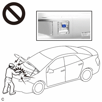
To prevent electric shock, make sure to remove the service plug grip to cut off the high voltage circuit before servicing the vehicle.
-
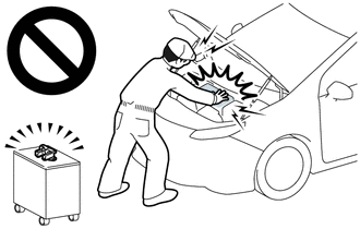
After removing the service plug grip from the HV battery, put it in your pocket to prevent other technicians from accidentally reconnecting it while you are working on the high-voltage system.
-
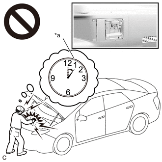
*a Without waiting for 10 minutes After removing the service plug grip, wait for at least 10 minutes before touching any of the high-voltage connectors or terminals. After waiting for 10 minutes, check the voltage at the terminals in the inspection point in the inverter with converter assembly. The voltage should be 0 V before beginning work.
Tip:Waiting for at least 10 minutes is required to discharge the high-voltage capacitor inside the inverter with converter assembly.
After turning the power switch off, waiting time may be required before disconnecting the cable from the negative (-) auxiliary battery terminal. Therefore, make sure to read the disconnecting the cable from the negative (-) auxiliary battery terminal notices before proceeding with work.
PROCEDURE
- Click here
CHECK DTC OUTPUT
-
Connect the GTS to the DLC3.
-
Turn the power switch on (IG).
-
Enter the following menus: Powertrain / Hybrid Control, Motor Generator and Engine / Trouble Codes.
-
Check for DTCs.
- Powertrain > Hybrid Control > Trouble Codes
-
-
- Powertrain > Motor Generator > Trouble Codes
-
-
- Powertrain > Engine > Trouble Codes
-
-
Result Result Proceed to P0A9300 only is output, or DTCs except the ones in the table below are also output. A DTCs of hybrid control system in the table below are output. B DTCs of motor generator control system in the table below are output. C DTCs of SFI system in the table below are output (w/ Grille shutter). D Table 2. Table 1 Malfunction Content System Relevant DTC Insulation malfunction Hybrid control system P1C7C49 Hybrid/EV Battery Voltage System Isolation (A/C Area) Internal Electronic Failure P1C7D49 Hybrid/EV Battery Voltage System Isolation (Hybrid/EV Battery Area) Internal Electronic Failure P1C7E49 Hybrid/EV Battery Voltage System Isolation (Transaxle Area) Internal Electronic Failure P1C7F49 Hybrid/EV Battery Voltage System Isolation (Direct Current Area) Internal Electronic Failure Table 3. Table 2 Malfunction Content System Relevant DTC Sensor and actuator circuit malfunction Hybrid control system P0C7396 Motor Electronics Coolant Pump "A" Component Internal Failure P314A31 Motor Electronics Coolant Pump "A" No Signal Motor generator control system P0A0011 Motor Electronics Coolant Temperature Sensor Circuit Short to Ground P0A0015 Motor Electronics Coolant Temperature Sensor Circuit Short to Battery or Open System malfunction SFI system P059F73 Active Grille Air Shutter "A" Actuator Stuck Closed P05A072 Active Grille Air Shutter "A" Actuator Stuck Open P05A211 Active Grille Air Shutter "A" Circuit Short to Ground P05A212 Active Grille Air Shutter "A" Circuit Short to Battery P05A213 Active Grille Air Shutter "A" Circuit Open P05A27E Active Grille Air Shutter "A" Actuator Stuck On P05A27F Active Grille Air Shutter "A" Actuator Stuck Off P05B112 Active Grille Air Shutter "B" Circuit Short to Battery P05B114 Active Grille Air Shutter "B" Circuit Short to Ground or Open P05B131 Active Grille Air Shutter "B" No Signal U028487 Lost Communication with Active Grille Air Shutter Module "A" Missing Message Tip:
-
P0A9300 may be output as a result of the malfunction indicated by the DTCs above.
-
-
The chart above is listed in inspection order of priority.
-
Check DTCs that are output at the same time by following the listed order. (The main cause of the malfunction can be determined without performing unnecessary inspections.)
-
-
Turn the power switch off.
- AClick here
- B
GO TO DTC CHART (HYBRID CONTROL SYSTEM)Click here
- C
GO TO DTC CHART (MOTOR GENERATOR CONTROL SYSTEM)Click here
- D
GO TO DTC CHART (SFI SYSTEM)Click here
-
- Click here
CHECK CONNECTOR CONNECTION CONDITION (INVERTER WITH CONVERTER ASSEMBLY CONNECTOR)
Result Result Proceed to OK A NG (The connector is not connected securely.) B NG (The terminals are not making secure contact or are deformed, or water or foreign matter exists in the connector.) C CAUTION:Be sure to wear insulated gloves.
-
Check that the service plug grip is not installed.
Note:After removing the service plug grip, do not turn the power switch on (READY), unless instructed by the repair manual because this may cause a malfunction.
-
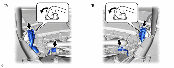
*A for LHD *B for RHD Check the connection condition of the low voltage connectors of the inverter with converter assembly and the contact pressure of each terminal. Check the terminals for deformation, and the connector for water and foreign matter.
Note:Before disconnecting the connector, confirm that it is properly connected by checking that the claws of the lock levers are engaged and that the connector cannot be pulled off.
OK - The connector is connected securely. - The terminals are not deformed and are connected securely. - No water or foreign matter in the connector. Result Result Proceed to OK A NG (The connector is not connected securely.) B NG (The terminals are not making secure contact or are deformed, or water or foreign matter exists in the connector.) C Tip:When connecting the connector, connect it with the lock levers raised. Rotate each lock lever downward and make sure that the connector is securely connected. When a lock lever is fully lowered, a click will be heard as its claw engages. After the click is heard, pull up on the connector to confirm that it is securely connected.
- AClick here
- B
CONNECT SECURELY
- C
REPAIR OR REPLACE HARNESS OR CONNECTOR
-
- Click here
CHECK COOLING SYSTEM
Tip:If the "Cooling System" inspection results are normal, perform the next step.
Result Proceed to NEXT
- NEXT
REPLACE HV COOLANTClick here
- NEXT