CAUTION / NOTICE / HINT
Perform "Inspection After Repairs" after replacing the air fuel ratio sensor.
-
w/ Canister Pump Module:
-
w/o Canister Pump Module:
PROCEDURE
- Click here
INSTALL AIR FUEL RATIO SENSOR (for Bank 1 Sensor 2)
-
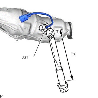
*a Torque Wrench Fulcrum Length Using SST, install the air fuel ratio sensor to the exhaust manifold assembly RH.
09224-00012 Specified tightening torque 44 N*m 449 kgf*cm 32 ft.*lbf Note:If the air fuel ratio sensor has been struck or dropped, replace it.
Tip:
-
Calculate the torque wrench reading when changing the fulcrum length of the torque wrench.
-
When using SST (fulcrum length of 30 mm (1.181 in.)) + torque wrench (fulcrum length of 180 mm (7.087 in.)): 37.7 N*m (384 kgf*cm, 28 ft.*lbf)
-
Perform "Inspection After Repairs" after replacing the air fuel ratio sensor.
-
-
w/ Canister Pump Module:
-
w/o Canister Pump Module:
-
-
-
- Click here
INSTALL AIR FUEL RATIO SENSOR (for Bank 2 Sensor 2)
-
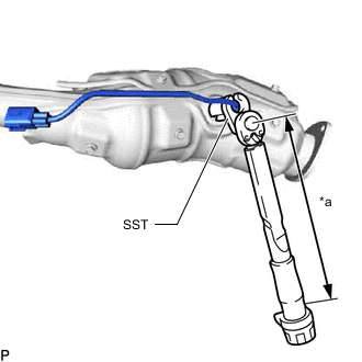
*a Torque Wrench Fulcrum Length Using SST, install the air fuel ratio sensor to the exhaust manifold assembly LH.
09224-00012 Specified tightening torque 44 N*m 449 kgf*cm 32 ft.*lbf Note:If the air fuel ratio sensor has been struck or dropped, replace it.
Tip:
-
Calculate the torque wrench reading when changing the fulcrum length of the torque wrench.
-
When using SST (fulcrum length of 30 mm (1.181 in.)) + torque wrench (fulcrum length of 180 mm (7.087 in.)): 37.7 N*m (384 kgf*cm, 28 ft.*lbf)
-
Perform "Inspection After Repairs" after replacing the air fuel ratio sensor.
-
-
w/ Canister Pump Module:
-
w/o Canister Pump Module:
-
-
-
- Click here
INSTALL EXHAUST MANIFOLD ASSEMBLY RH
- Click here
INSTALL EXHAUST MANIFOLD ASSEMBLY LH
- Click here
INSTALL AIR FUEL RATIO SENSOR (for Bank 1 Sensor 1)
-
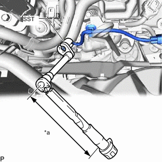
*a Torque Wrench Fulcrum Length Using SST, install the air fuel ratio sensor to the exhaust manifold assembly RH.
09224-00012 Specified tightening torque 44 N*m 449 kgf*cm 32 ft.*lbf Note:If the air fuel ratio sensor has been struck or dropped, replace it.
Tip:
-
Calculate the torque wrench reading when changing the fulcrum length of the torque wrench.
-
When using SST (fulcrum length of 30 mm (1.181 in.)) + torque wrench (fulcrum length of 180 mm (7.087 in.)): 37.7 N*m (384 kgf*cm, 28 ft.*lbf)
-
Perform "Inspection After Repairs" after replacing the air fuel ratio sensor.
-
-
w/ Canister Pump Module:
-
w/o Canister Pump Module:
-
-
-
Attach the 3 wire harness clamps.
-
Connect the air fuel ratio sensor connector.
-
- Click here
INSTALL AIR FUEL RATIO SENSOR (for Bank 2 Sensor 1)
-
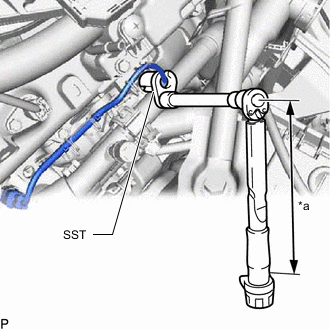
*a Torque Wrench Fulcrum Length Using SST, install the air fuel ratio sensor to the exhaust manifold assembly LH.
09224-00012 Specified tightening torque 44 N*m 449 kgf*cm 32 ft.*lbf Note:If the air fuel ratio sensor has been struck or dropped, replace it.
Tip:
-
Calculate the torque wrench reading when changing the fulcrum length of the torque wrench.
-
When using SST (fulcrum length of 30 mm (1.181 in.)) + torque wrench (fulcrum length of 180 mm (7.087 in.)): 37.7 N*m (384 kgf*cm, 28 ft.*lbf)
-
Perform "Inspection After Repairs" after replacing the air fuel ratio sensor.
-
-
w/ Canister Pump Module:
-
w/o Canister Pump Module:
-
-
-
Attach the 4 wire harness clamps.
-
Connect the air fuel ratio sensor connector.
-
- Click here
INSTALL INVERTER MOTOR CABLE BRACKET ASSEMBLY (for LHD)
- Click here
INSTALL FENDER APRON BRACE SUB-ASSEMBLY RH (for LHD)
- Click here
INSTALL INVERTER MOTOR CABLE BRACKET ASSEMBLY (for RHD)
- Click here
INSTALL FENDER APRON BRACE SUB-ASSEMBLY LH (for RHD)
- Click here
INSTALL LOWER RADIATOR AIR DEFLECTOR
- Click here
INSTALL UPPER RADIATOR SUPPORT SEAL
- Click here
INSTALL RADIATOR COVER PLATE
- Click here
INSTALL V-BANK COVER SUB-ASSEMBLY