ECM REMOVAL
CAUTION / NOTICE / HINT
The necessary procedures (adjustment, calibration, initialization or registration) that must be performed after parts are removed and installed, or replaced during ECM removal/installation are shown below.
| Replaced Part or Performed Procedure | Necessary Procedure | Effect/Inoperative Function when Necessary Procedure not Performed | Link |
|---|---|---|---|
| Auxiliary battery terminal is disconnected/reconnected | Memorize steering angle neutral point | LKA/LDA system (for Mono camera type) |
|
| Lane control system (for Stereo camera type) | |||
| Parking support brake system* | |||
| Pre-collision system (for Mono camera type) | |||
| Pre-collision system (for Stereo camera type) | |||
| Adaptive high beam system | |||
Lighting system (EXT) |
|||
| Variable gear ratio steering system | |||
| Parking assist monitor system | |||
| Panoramic view monitor system | |||
| Initialize Rear Door Sunshade System | Rear door sunshade system | ||
| Initialize power trunk lid system | Power trunk lid system | ||
| ECM | Vehicle Identification Number (VIN) registration | DTC P063051 is output |
|
Click here Click here
Note
After turning the power switch off, waiting time may be required before disconnecting the cable from the negative (-) battery terminal. Therefore, make sure to read the disconnecting the cable from the negative (-) battery terminal notices before proceeding with work.
PROCEDURE
-
DISCONNECT CABLE FROM NEGATIVE AUXILIARY BATTERY TERMINAL
Note
When disconnecting the cable, some systems need to be initialized after the cable is reconnected.
-
REMOVE RADIATOR COVER PLATE
-
REMOVE UPPER RADIATOR SUPPORT SEAL
-
REMOVE LOWER RADIATOR AIR DEFLECTOR
-
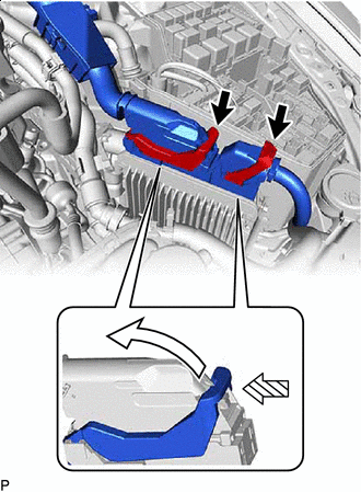
REMOVE ECM
-

Raise 
Push Push in the locks on the 2 levers, raise the 2 levers, and disconnect the 2 ECM connectors.
Note
After disconnecting the connectors, make sure that dirt, water or other foreign matter does not contact the connecting part of the connectors.
-
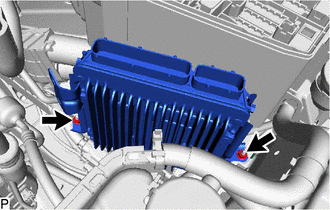
Remove the 2 nuts and ECM.
Note
If the ECM has been struck or dropped, replace it.
-
-
REMOVE NO. 1 ECM BRACKET
-
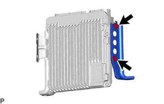
Remove the 2 bolts and No. 1 ECM bracket from the ECM.
Note
If the ECM has been struck or dropped, replace it.
-
-
REMOVE NO. 2 ECM BRACKET
-
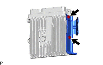
Remove the 2 bolts and No. 2 ECM bracket from the ECM.
Note
If the ECM has been struck or dropped, replace it.
-