CAUTION / NOTICE / HINT
The necessary procedures (adjustment, calibration, initialization, or registration) that must be performed after parts are removed, installed, or replaced during the rear axle hub removal/installation are shown below.
| Necessary Procedure After Parts Removed/Installed/Replaced | ||||||||||||||||||||||
|---|---|---|---|---|---|---|---|---|---|---|---|---|---|---|---|---|---|---|---|---|---|---|
|
-
Use the same procedure for the RH and LH side.
-
The following procedure is for the LH side.
PROCEDURE
- Click here
AIR SUSPENSION CONTROL PROHIBITED (w/ Air Suspension)
- Click here
DISCONNECT BRAKE BOOSTER PUMP CONNECTOR
- Click here
REMOVE REAR WHEEL
- Click here
DISCONNECT REAR HEIGHT CONTROL SENSOR SUB-ASSEMBLY LH
-
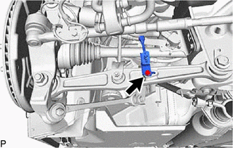
Disconnect the bolt and rear height control sensor sub-assembly LH.
-
- Click here
DISCONNECT REAR STABILIZER LINK ASSEMBLY LH
- Click here
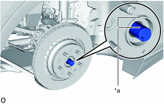
REMOVE REAR AXLE SHAFT NUT LH
-
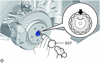
Using SST and a hammer, release the staked part of the rear axle shaft nut LH.
09930-00010 Note:
-
Set SST in the groove with its flat surface facing upward.
-
Do not grind the tip of SST with a grinder or other tools.
-
Fully unstake the rear axle shaft nut LH.
-
Do not damage the threads of the rear drive shaft assembly LH.
-
-
Using a 32 mm socket wrench, remove the rear axle shaft nut LH.
-
- Click here
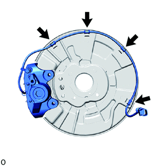
DISCONNECT SKID CONTROL SENSOR WIRE
-
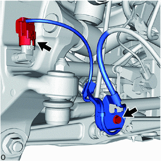
for LH Side:
-
Disconnect the speed sensor connector from the speed sensor LH.
Note:
-
Be careful not to damage the speed sensor.
-
Prevent foreign matter from adhering to the speed sensor.
-
-
Remove the bolt and sensor clamp.
-
-
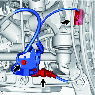
for RH Side:
-
Disconnect the speed sensor connector from the speed sensor RH.
Note:
-
Be careful not to damage the speed sensor.
-
Prevent foreign matter from adhering to the speed sensor.
-
-
Disconnect the pad wear indicator connector.
-
Remove the bolt and sensor clamp.
-
-
- Click here
REMOVE REAR SPEED SENSOR LH
- Click here
DISCONNECT REAR DISC BRAKE CYLINDER ASSEMBLY
-
for RH side:
-
Detach the 2 clamps to disconnect the pad wear indicator assembly.
-
-
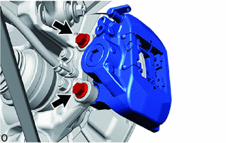
Remove the 2 bolts and disconnect disc brake cylinder assembly LH from the steering knuckle.
Note:Use wire or an equivalent tool to keep the rear disc brake cylinder assembly LH from hanging down by the flexible hose.
-
- Click here
REMOVE PARKING BRAKE SHOE ADJUSTING HOLE PLUG
-
for 4-Pot Caliper:
-
except 4-Pot Caliper:
-
- Click here
REMOVE REAR DISC LH
-
for 4-Pot Caliper:
-
except 4-Pot Caliper:
-
- Click here
REMOVE PARKING BRAKE
- Click here
DISCONNECT REAR SHOCK ABSORBER ASSEMBLY LH (w/o Air Suspension)
-

Remove the nut from the rear shock absorber with coil spring (lower side).
-


Remove in this Direction (1) 
Remove in this Direction (2) Remove the rear shock absorber with coil spring and washer as shown in the illustration.
-
- Click here
DISCONNECT REAR PNEUMATIC CYLINDER ASSEMBLY LH WITH SHOCK ABSORBER (w/ Air Suspension)
Tip:Use the same procedure for the rear shock absorber assebmly LH.
- Click here
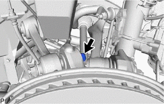
DISCONNECT REAR NO. 2 SUSPENSION ARM ASSEMBLY LH
-
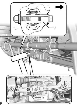
*a A *b Arm *c Slide Pin *d Axle Carrier 
Front of the Vehicle Using a plastic-faced hammer or equivalent, strike the part labeled A from the rear of the vehicle to maintain the clearance at the slide pin area.
Note:Be careful not to damage the arm.
-
Remove the nut, bolt and washer.
-
- Click here
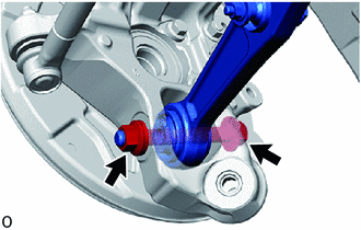
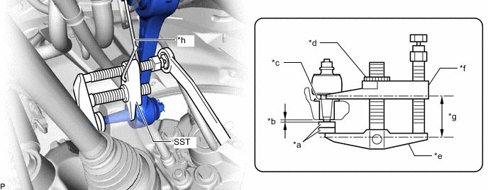
DISCONNECT LOWER CONTROL ARM ASSEMBLY LH
-
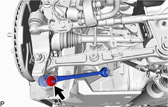
Remove the nut.
-
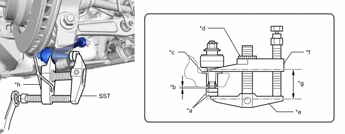
*a SST (Spacer B) *b 1 mm (0.0394 in.) *c Spacer *d Center Nut *e Body *f Claw *g Parallel *h String Install 2 SST (spacer B) onto the lower control arm assembly LH so that there is a space of approximately 1 mm (0.0394 in.) between the arm and spacers.
09960-20010 09961-02060 Note:
-
Make sure to install the spacers (SST spacer B) as the rear axle carrier sub-assembly LH spacer may shift.
-
As SST may become damaged, make sure the space between the arm and spacers is not 1 mm (0.0394 in.) or less.
-
-
Using SST, disconnect the lower control arm assembly LH from the rear axle carrier sub-assembly LH.
09960-20010 09961-02010 Note:
-
Apply molybdenum grease to the bolt threads and end of SST bolt.
-
Do not damage the dust cover.
-
As the dust cover may be damaged, adjust SST with the center nut so that the body and claw are parallel.
-
Make sure to tie the string of SST to the vehicle to prevent SST from dropping.
-
-
- Click here
DISCONNECT TOE CONTROL LINK SUB-ASSEMBLY LH (w/o Dynamic Rear Steering)
-
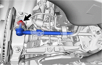
Remove the nut.
-
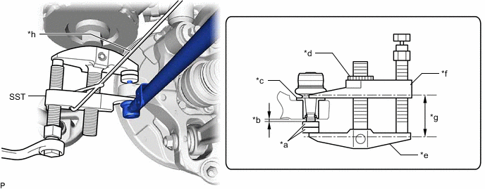
*a SST (Spacer B) *b 1 mm (0.0394 in.) *c Spacer *d Center Nut *e Body *f Claw *g Parallel *h String Install 2 SST (spacer B) onto the toe control link sub-assembly LH so that there is a space of approximately 1 mm (0.0394 in.) between the arm and spacers.
09960-20010 09961-02060 Note:
-
Make sure to install the spacers (SST spacer B) as the rear axle carrier sub-assembly LH spacer may shift.
-
As SST may become damaged, make sure the space between the arm and spacers is not 1 mm (0.0394 in.) or less.
-
-
Using SST, disconnect the toe control link sub-assembly LH from the rear axle carrier sub-assembly LH.
09960-20010 09961-02010 Note:
-
Apply molybdenum grease to the bolt threads and end of SST bolt.
-
Do not damage the dust cover.
-
As the dust cover may be damaged, adjust SST with the center nut so that the body and claw are parallel.
-
Make sure to tie the string of SST to the vehicle to prevent SST from dropping.
-
-
- Click here
DISCONNECT REAR STEERING TIE ROD ASSEMBLY LH (w/ Dynamic Rear Steering)
- Click here
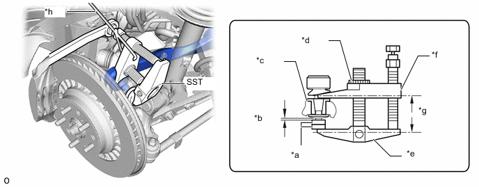
DISCONNECT REAR NO. 1 SUSPENSION ARM ASSEMBLY LH
-
Remove the nut.
-
*a SST (Spacer A) *b 1 mm (0.0394 in.) *c Spacer *d Center Nut *e Body *f Claw *g Parallel *h String Install 2 SST (spacer A) onto the rear No. 1 suspension arm assembly LH so that there is a space of approximately 1 mm (0.0394 in.) between the arm and spacers.
09960-20010 09961-02050 Note:
-
Make sure to install the spacers (SST spacer A) as the rear axle carrier sub-assembly LH spacer may shift.
-
As SST may become damaged, make sure the space between the arm and spacers is not 1 mm (0.0394 in.) or less.
-
-
Using SST, disconnect the rear No. 1 suspension arm assembly LH from the rear axle carrier sub-assembly LH.
09960-20010 09961-02010 Note:
-
Apply molybdenum grease to the bolt threads and end of SST bolt.
-
Do not damage the dust cover.
-
As the dust cover may be damaged, adjust SST with the center nut so that the body and claw are parallel.
-
Make sure to tie the string of SST to the vehicle to prevent SST from dropping.
-
-
- Click here
DISCONNECT REAR UPPER CONTROL ARM ASSEMBLY LH
-
Remove the nut.
-
*a SST (Spacer A) *b 1 mm (0.0394 in.) *c Spacer *d Center Nut *e Body *f Claw *g Parallel *h String Install 2 SST (spacer A) onto the rear upper control arm assembly LH so that there is a space of approximately 1 mm (0.0394 in.) between the arm and spacers.
09960-20010 09961-02050 Note:
-
Make sure to install the spacers (SST spacer A) as the rear axle carrier sub-assembly LH spacer may shift.
-
As SST may become damaged, make sure the space between the arm and spacers is not 1 mm (0.0394 in.) or less.
-
-
Using SST, disconnect the rear upper control arm assembly LH from the rear axle carrier sub-assembly LH.
09960-20010 09961-02010 Note:
-
Apply molybdenum grease to the bolt threads and end of SST bolt.
-
Do not damage the dust cover.
-
As the dust cover may be damaged, adjust SST with the center nut so that the body and claw are parallel.
-
Make sure to tie the string of SST to the vehicle to prevent SST from dropping.
-
-
- Click here
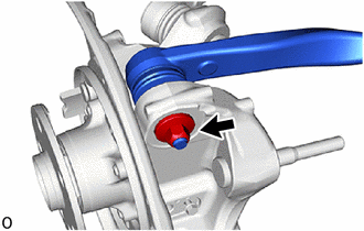
REMOVE REAR AXLE ASSEMBLY
-
*a Matchmark Place matchmarks on the rear axle hub and bearing assembly LH and rear drive shaft assembly LH as shown in the illustration.
-
Using a plastic-faced hammer, lightly tap the end of the drive shaft assembly and disengage the drive shaft and rear axle carrier.
Tip:If the connection is stiff, tap the end of the drive shaft using a brass bar and hammer.
-
Pull the rear axle assembly LH toward the vehicle exterior while supporting the rear drive shaft assembly.
Note:
-
Do not damage the drive shaft outboard joint boot.
-
Suspend the drive shaft assembly with rope, wire or an equivalent tool.
-
-
- Click here
REMOVE REAR NO. 1 WHEEL BEARING DUST DEFLECTOR LH
-
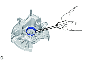
Using a screwdriver, remove the rear No. 1 wheel bearing dust deflector LH from the rear axle carrier.
Note:The rear axle carrier is made from aluminum. Therefore, take care that it does not become dented.
-
- Click here
REMOVE REAR AXLE HUB AND BEARING ASSEMBLY LH
-
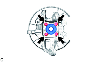
Remove the 4 bolts and rear axle hub and bearing assembly LH from the rear axle carrier.
-
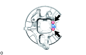
Remove the 2 nuts and parking brake anchor block sub-assembly, cable support bracket and parking brake plate from the rear axle carrier.
-