CAUTION / NOTICE / HINT
The necessary procedures (adjustment, calibration, initialization, or registration) that must be performed after parts are removed, installed, or replaced during the rear drive shaft assembly removal/installation are shown below.
| Replacement Part or Procedure | Necessary Procedure | Effect/Inoperative when not Performed | Link |
|---|---|---|---|
|
Parking brake bedding | Electric parking brake system | |
| Rear steering link assembly or rear suspension have been removed/installed, replaced, or adjusted |
|
Steering wheel off-center | |
| Suspension, tires, etc |
|
Parking support brake system | |
|
Panoramic view monitor system | ||
| Rear television camera assembly optical axis (Back camera position setting) | Parking assist monitor system |
PROCEDURE
- Click here
REMOVE NO. 2 DIFFERENTIAL SUPPORT PROTECTOR
-
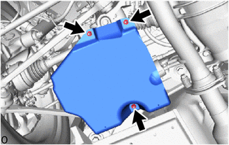
Remove the 3 nuts and No. 2 differential support protector.
-
- Click here
REMOVE NO. 1 DIFFERENTIAL SUPPORT PROTECTOR
Tip:Use the same procedure described for the No. 2 differential support protector.
- Click here
REMOVE REAR SUSPENSION MEMBER BRACE LH
-
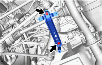
Remove the 2 bolts and rear suspension member brace LH.
-
- Click here
REMOVE REAR SUSPENSION MEMBER BRACE RH
Tip:Use the same procedure as for the LH side.
- Click here
REMOVE REAR AXLE ASSEMBLY LH
- Click here
REMOVE REAR AXLE ASSEMBLY RH
Tip:Use the same procedure as for the LH side.
- Click here
REMOVE REAR DRIVE SHAFT ASSEMBLY LH
-
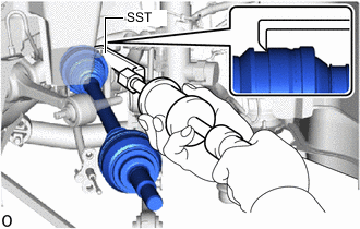
Using SST, remove the rear drive shaft assembly LH.
09520-01010 09520-24010 09520-32040 Note:
-
Do not damage the oil seal, boot and dust cover.
-
Do not drop the rear drive shaft assembly LH.
-
When carrying the rear drive shaft assembly LH, hold it horizontally.
Tip:Hook the SST claw at the position shown in the illustration to remove the rear drive shaft assembly LH.
-
-
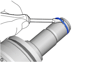
Using a screwdriver, remove the shaft snap ring.
Note:Do not damage the spline of the rear drive shaft assembly LH.
-
- Click here
REMOVE REAR DRIVE SHAFT ASSEMBLY RH
Tip:Use the same procedure as for the LH side.