CAUTION / NOTICE / HINT
The necessary procedures (adjustment, calibration, initialization, or registration) that must be performed after parts are removed, installed, or replaced during the front drive shaft assembly removal/installation are shown below.
| Necessary Procedure After Parts Removed/Installed/Replaced | ||||||||||||||
|---|---|---|---|---|---|---|---|---|---|---|---|---|---|---|
|
PROCEDURE
- Click here
DRAIN DIFFERENTIAL OIL
- Click here
REMOVE FRONT AXLE ASSEMBLY LH
- Click here
REMOVE FRONT AXLE ASSEMBLY RH
- Click here
REMOVE FRONT DRIVE SHAFT ASSEMBLY LH
-
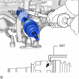
Using SST, remove the front drive shaft assembly LH.
09520-01010 09520-24010 09520-32040 Note:
-
Do not damage the differential side gear shaft oil seal LH, drive shaft inboard joint boot and front drive shaft dust cover.
-
Do not drop the front drive shaft assembly LH.
-
When carrying the front drive shaft assembly LH, hold it horizontally.
Tip:Hook the SST claw at the position shown in the illustration to remove the front drive shaft assembly LH.
-
-
- Click here
INSTALL FRONT DRIVE SHAFT ASSEMBLY RH
-
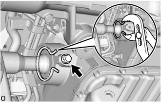
Using water pump pliers, remove the drive shaft bearing bracket hole snap ring.
-
Remove the No. 1 drive shaft bearing bracket setting bolt and front drive shaft assembly RH.
Note:
-
Do not to damage the drive shaft inboard joint boot and oil seal.
-
Do not drop the front drive shaft assembly RH.
Tip:Determine whether the front drive shaft assembly LH is completely tapped in by checking for changes in the tapping sound or the reaction of the brass bar.
-
-
- Click here
REMOVE FRONT DRIVE SHAFT HOLE SNAP RING LH
-
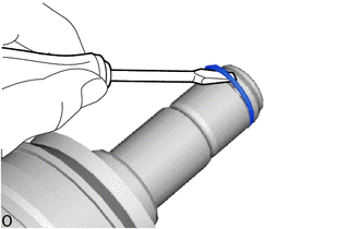
Using a screwdriver, remove the front drive shaft hole snap ring LH.
Note:Do not damage the spline of the inboard joint assembly LH.
-