OIL PUMP INSTALLATION
PROCEDURE
-
INSTALL OIL WITH MOTOR PUMP ASSEMBLY
-
Install a new gasket to the oil with motor pump assembly.
-
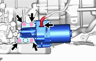
Install the oil with motor pump assembly with the 4 bolts to the hybrid vehicle transmission assembly.
- Torque:
- 31.5 N*m { 321 kgf*cm, 23 ft.*lbf }
-
Connect the transmission breather hose to the oil with motor pump assembly.
-
-
CONNECT WIRE HARNESS
-
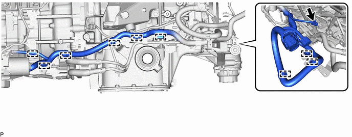
Connect the 9 wire harness clamps.
-
Connect the oil pump thermistor connector.
-
-
CONNECT CONNECTOR
-
INSTALL TRANSMISSION OIL PUMP INSULATOR BRACKET
-
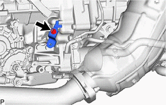
Install the transmission oil pump insulator bracket with the bolt.
- Torque:
- 7.0 N*m { 71 kgf*cm, 62 in.*lbf }
-
-
INSTALL TRANSMISSION OIL PUMP INSULATOR
-
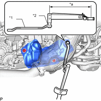
*1 Long Offset Wrench (10 x 12) *2 12 mm Hexagon Socket Wrench *a Fulcrum Length Install the transmission oil pump insulator with the 3 bolts.
- Torque:
- Specified tightening torque
- 8.0 N*m { 82 kgf*cm, 71 in.*lbf }
Tech Tips
-
Calculate the torque wrench reading when changing the fulcrum length of the torque wrench.
-
When using a long offset wrench (fulcrum length of 206.25 mm (8.120 in.)) + torque wrench (fulcrum length of 185 mm (7.284 in.)): 3.8 N*m (39 kgf*cm, 34 in.*lbf)
-
-
INSTALL NO. 1 EXHAUST PIPE SUPPORT BRACKET SUB-ASSEMBLY
-
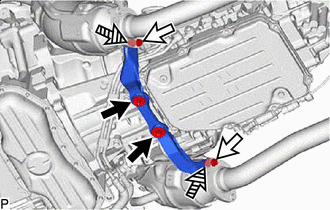

Bolt (A) 
Bolt (B) 
Nut Temporarily install the No. 1 exhaust pipe support bracket sub-assembly with the 2 bolts (A) to the hybrid vehicle transmission assembly.
-
Connect the No. 1 exhaust pipe support bracket sub-assembly to the exhaust manifold assembly LH and exhaust manifold assembly RH with 2 new bolts (B) and 2 new nuts.
- Torque:
- 39 N*m { 398 kgf*cm, 29 ft.*lbf }
-
Tighten the 2 bolts (A).
- Torque:
- 43 N*m { 438 kgf*cm, 32 ft.*lbf }
-
-
INSTALL AIR CLEANER ASSEMBLY
-
INSTALL NO. 1 AIR CLEANER INLET
-
INSTALL RADIATOR SUPPORT TO CROSS MEMBER BRACE SUB-ASSEMBLY RH
-
INSTALL LOWER RADIATOR AIR DEFLECTOR
-
INSTALL RADIATOR COVER PLATE
-
INSTALL V-BANK COVER SUB-ASSEMBLY
-
ADD TRANSMISSION FLUID
-
ADJUST TRANSMISSION FLUID
-
INSTALL NO. 2 ENGINE UNDER COVER ASSEMBLY
-
INSTALL TRANSMISSION UNDER COVER
-
CONNECT CABLE TO NEGATIVE AUXILIARY BATTERY TERMINAL