DRIVING SUPPORT ECU INSTALLATION
PROCEDURE
-
INSTALL DRIVING SUPPORT ECU ASSEMBLY
Note
Do not use a driving support ECU if it has been dropped or has been subjected to any strong impact.
-
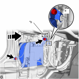
*a Wire Harness Clamp *b Hook 
Install in this Direction for Stereo Camera Type:
Note
Do not use a driving support ECU if it has been dropped or has been subjected to any strong impact.
-
Install the driving support ECU in the direction of the arrow shown in the illustration and attach the hook.
-
Install the 2 bolts.
- Torque:
- 10 N*m { 102 kgf*cm, 7 ft.*lbf }
-
Attach the wire harness clamp.
-
-
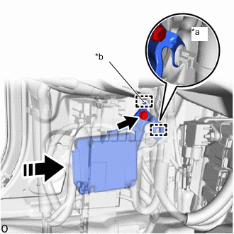
*a Wire Harness Clamp *b Hook Install in this Direction for Mono Camera Type:
Note
Do not use a driving support ECU if it has been dropped or has been subjected to any strong impact.
-
Install the driving support ECU in the direction of the arrow shown in the illustration and attach the hook.
-
Install the bolt.
- Torque:
- 10 N*m { 102 kgf*cm, 7 ft.*lbf }
-
Attach the wire harness clamp.
-
-
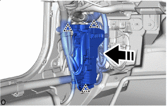
Install in this Direction Attach the clip as shown in the illustration to install the connector holder.
-
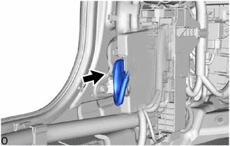
Connect the connector.
-
-
INSTALL NO. 1 INSTRUMENT PANEL UNDER COVER SUB-ASSEMBLY (for LHD)
-
INSTALL NO. 2 INSTRUMENT PANEL UNDER COVER SUB-ASSEMBLY (for RHD)
-
INSTALL COWL SIDE TRIM BOARD LH
-
INSTALL FRONT DOOR SCUFF PLATE LH
-
CONNECT CABLE TO NEGATIVE AUXILIARY BATTERY TERMINAL
Note
When disconnecting the cable, some systems need to be initialized after the cable is reconnected.
-
INSTALL LUGGAGE COMPARTMENT MAT SUB-ASSEMBLY