ADAPTIVE VARIABLE SUSPENSION SYSTEM, Diagnostic DTC:C1711, C1712, C1713, C1714
| DTC Code | DTC Name |
|---|---|
| C1711 | Front Height Control Sensor RH Circuit Malfunction |
| C1712 | Front Height Control Sensor LH Circuit Malfunction |
| C1713 | Rear Height Control Sensor RH Circuit Malfunction |
| C1714 | Rear Height Control Sensor LH Circuit Malfunction |
DESCRIPTION
The height control sensor sub-assembly changes the resistance according to the change in vehicle height. The absorber control ECU outputs a fixed voltage of 5 V to the height control sensor sub-assembly SHB terminal. If the sensor's resistance value changes, the sensor's voltage changes accordingly. The suspension ECU then inputs the voltage value from the sensor to detect the vehicle height change.
| DTC No. | Detection Item | DTC Detection Condition | Trouble Area | Warning Indicate | Memory |
|---|---|---|---|---|---|
| C1711 | Front Height Control Sensor RH Circuit Malfunction | One of the following conditions is met:
|
|
Does not come on | Yes |
| C1712 | Front Height Control Sensor LH Circuit Malfunction | One of the following conditions is met:
|
|
Does not come on | Yes |
| C1713 | Rear Height Control Sensor RH Circuit Malfunction | One of the following conditions is met:
|
|
Does not come on | Yes |
| C1714 | Rear Height Control Sensor LH Circuit Malfunction | One of the following conditions is met:
|
|
Does not come on | Yes |
-
*: w/o Air Suspension
| Vehicle Condition | ||||||
|---|---|---|---|---|---|---|
| Pattern 1 | Pattern 2 | Pattern 3 | Pattern 4 | Pattern 5 | ||
| Diagnosis Condition | Power switch is on (IG) | ○ | ○ | ○ | ○ | ○ |
| Malfunction Status | Power source voltage is 4.3 V or less* | ○ | - | - | - | - |
| Power source voltage is 5.5 V or higher* | - | ○ | - | - | - | |
| Output voltage is 0.3 V or less | - | - | ○ | - | - | |
| Output voltage is 4.7 V or higher | - | - | - | ○ | - | |
| Height control sensor stuck | - | - | - | - | ○ | |
| Detection Time | 0.5 seconds or more | 0.5 seconds or more | 1 second or more | 1 second or more | - | |
| Number of Trips | 1 trip | 1 trip | 1 trip | 1 trip | 1 trip | |
Tech Tips
DTC will be output when conditions for either of the patterns in the table above are met.
WIRING DIAGRAM
Figure 1. w/o Air Suspension:
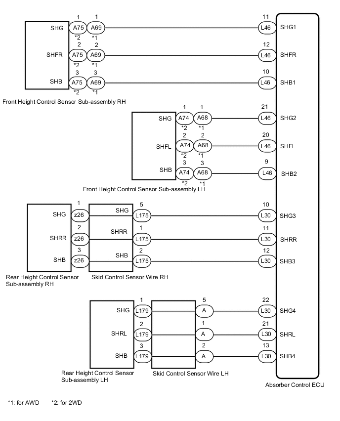
Figure 2. w/ Air Suspension:
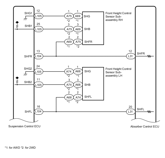
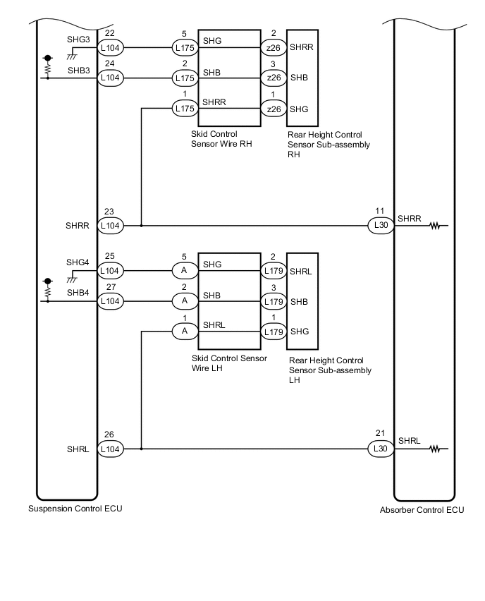
Figure 3. w/ Air Suspension:
CAUTION / NOTICE / HINT
Note
-
Before performing troubleshooting, inspect the connectors of related circuits.
-
If DTC C1782 (Power Source Voltage Malfunction) is output at the same time, perform troubleshooting for C1782 first.
-
Before replacing the absorber control ECU, perform all of the following:
-
Symptom simulation.
-
DTC inspection.
-
GTS inspection.
-
If no malfunctions are found in other areas, replace the absorber control ECU.
-
After replacing the absorber control ECU with a new one, perform registration of vehicle identification information.
PROCEDURE
-
CHECK SUSPENSION TYPE
-
Check the suspension type.
Result Result Proceed to w/o Air Suspension A w/ Air Suspension B
B 
CHECK FOR DTCS Click here
A 
-
-
CHECK HEIGHT CONTROL SENSOR SUB-ASSEMBLY INSTALLATION CONDITION
-
Check the height control sensor sub-assembly installation condition and make sure that there are no loose installation bolts and foreign matter trapped between the sensor and body.
OK Installed correctly. Result Proceed to OK NG
NG 
INSTALL HEIGHT CONTROL SENSOR SUB-ASSEMBLY CORRECTLY for Front Side : Click here
INSTALL HEIGHT CONTROL SENSOR SUB-ASSEMBLY CORRECTLY for Rear Side : Click hereOK
-
-
INSPECT HEIGHT CONTROL SENSOR SUB-ASSEMBLY (FRONT OR REAR)
-
For Front Side.
-
Inspect the front height control sensor sub-assembly RH or front height control sensor sub-assembly LH.
-
-
For Rear Side.
-
Inspect the rear height control sensor sub-assembly RH or rear height control sensor sub-assembly LH.
Result Result Proceed to OK (for Front Side) A OK (for Rear Side) B Front height control sensor sub-assembly RH malfunction C Front height control sensor sub-assembly LH malfunction D Rear height control sensor sub-assembly RH malfunction E Rear height control sensor sub-assembly LH malfunction F -
B
CHECK HARNESS AND CONNECTOR (REAR HEIGHT CONTROL SENSOR SUB-ASSEMBLY - ABSORBER CONTROL ECU) Click here
C
REPLACE FRONT HEIGHT CONTROL SENSOR SUB-ASSEMBLY RH Click here
D
REPLACE FRONT HEIGHT CONTROL SENSOR SUB-ASSEMBLY LH Click here
E
REPLACE REAR HEIGHT CONTROL SENSOR SUB-ASSEMBLY RH Click here
F
REPLACE REAR HEIGHT CONTROL SENSOR SUB-ASSEMBLY LH Click here
A
-
-
CHECK HARNESS AND CONNECTOR (FRONT HEIGHT CONTROL SENSOR SUB-ASSEMBLY - ABSORBER CONTROL ECU)
-
Check the front height control sensor sub-assembly RH harness and connector.
-
Turn the power switch off.
-
Disconnect the A69*1 or A75*2 front height control sensor sub-assembly RH connector.
-
*1: for AWD
-
*2: for 2WD
-
-
Disconnect the L46 absorber control ECU connector.
-
Measure the resistance according to the value(s) in the table below.
Standard Resistance for AWD: Tester Connection Condition Specified Condition A69-1 (SHG) - L46-11 (SHG1) Always Below 1 Ω A69-2 (SHFR) - L46-12 (SHFR) A69-3 (SHB) - L46-10 (SHB1) A69-1 (SHG) or L46-11 (SHG1) - Body ground Always 10 kΩ or higher A69-2 (SHFR) or L46-12 (SHFR) - Body ground A69-3 (SHB) or L46-10 (SHB1) - Body ground for 2WD: Tester Connection Condition Specified Condition A75-1 (SHG) - L46-11 (SHG1) Always Below 1 Ω A75-2 (SHFR) - L46-12 (SHFR) A75-3 (SHB) - L46-10 (SHB1) A75-1 (SHG) or L46-11 (SHG1) - Body ground Always 10 kΩ or higher A75-2 (SHFR) or L46-12 (SHFR) - Body ground A75-3 (SHB) or L46-10 (SHB1) - Body ground
-
-
Check the front height control sensor sub-assembly LH harness and connector.
-
Turn the power switch off.
-
Disconnect the A68*1 or A74*2 front height control sensor sub-assembly LH connector.
-
*1: for AWD
-
*2: for 2WD
-
-
Disconnect the L46 absorber control ECU connector.
-
Measure the resistance according to the value(s) in the table below.
Standard Resistance for AWD: Tester Connection Condition Specified Condition A68-1 (SHG) - L46-21 (SHG2) Always Below 1 Ω A68-2 (SHFL) - L46-20 (SHFL) A68-3 (SHB) - L46-9 (SHB2) A68-1 (SHG) or L46-21 (SHG2) - Body ground Always 10 kΩ or higher A68-2 (SHFL) or L46-20 (SHFL) - Body ground A68-3 (SHB) or L46-9 (SHB2) - Body ground for 2WD: Tester Connection Condition Specified Condition A74-1 (SHG) - L46-21 (SHG2) Always Below 1 Ω A74-2 (SHFL) - L46-20 (SHFL) A74-3 (SHB) - L46-9 (SHB2) A74-1 (SHG) or L46-21 (SHG2) - Body ground Always 10 kΩ or higher A74-2 (SHFL) or L46-20 (SHFL) - Body ground A74-3 (SHB) or L46-9 (SHB2) - Body ground
Result Result OK NG -
OK
REPLACE ABSORBER CONTROL ECU Click here
NG
REPAIR OR REPLACE HARNESS AND CONNECTOR
-
-
CHECK HARNESS AND CONNECTOR (REAR HEIGHT CONTROL SENSOR SUB-ASSEMBLY - ABSORBER CONTROL ECU)
-
Check the rear height control sensor sub-assembly RH harness and connector.
-
Turn the power switch off.
-
Disconnect the L30 absorber control ECU connector.
-
Disconnect the z26 skid control sensor wire RH connector.
-
Measure the resistance according to the value(s) in the table below.
Standard Resistance Tester Connection Condition Specified Condition z26-1 (SHG) - L30-10 (SHG3) Always Below 1 Ω z26-2 (SHRR) - L30-11 (SHRR) z26-3 (SHB) - L30-12 (SHB3) z26-1 (SHG) or L30-10 (SHG3) - Body ground Always 10 kΩ or higher z26-2 (SHRR) or L30-11 (SHRR) - Body ground z26-3 (SHB) or L30-12 (SHB3) - Body ground
-
-
Check the rear height control sensor sub-assembly LH harness and connector.
-
Turn the power switch off.
-
Disconnect the L30 absorber control ECU connector.
-
Disconnect the L179 skid control sensor wire LH connector.
-
Measure the resistance according to the value(s) in the table below.
Standard Resistance Tester Connection Condition Specified Condition L179-1 (SHG) - L30-22 (SHG4) Always Below 1 Ω L179-2 (SHRL) - L30-21 (SHRL) L179-3 (SHB) - L30-13 (SHB4) L179-1 (SHG) or L30-22 (SHG4) - Body ground Always 10 kΩ or higher L179-2 (SHRL) or L30-21 (SHRL) - Body ground L179-3 (SHB) or L30-13 (SHB4) - Body ground
Result Result OK NG -
OK
REPLACE ABSORBER CONTROL ECU Click here
NG
-
-
INSPECT SKID CONTROL SENSOR WIRE
-
Turn the power switch off.
-
Disconnect the L175 or A skid control sensor wire connector.
-
Measure the resistance according to the value(s) in the table below.
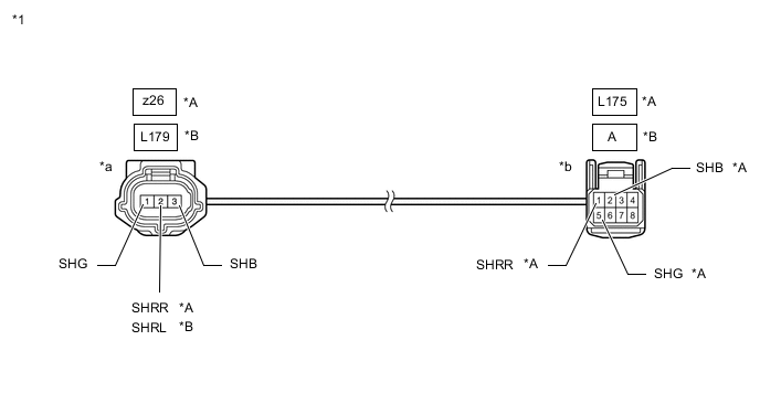
*A RH *B LH *1 Skid Control Sensor Wire - - *a Front view of wire harness connector
(to Rear Height Control Sensor Sub-assembly Side Connector)
*b Front view of wire harness connector
(to Vehicle Side Connector)
Standard Resistance for RH Tester Connection Condition Specified Condition L175 -1 (SHRR) - z26 -2 (SHRR) Always Below 1 Ω L175 -2 (SHB) - z26 -3 (SHB) L175 -5 (SHG) - z26 -1 (SHG) L175 -1 (SHRR) or z26 -2 (SHRR) - Body ground and other terminals Always 10 kΩ or higher L175 -2 (SHB) or z26 -3 (SHB) - Body ground and other terminals L175 -5 (SHG) or z26 -1 (SHG) - Body ground and other terminals Standard Resistance for LH Tester Connection Condition Specified Condition A -1 - L179 -2 (SHRL) Always Below 1 Ω A -2 - L179 -3 (SHB) A-5 - L179 -1 (SHG) A -1 or L179 -2 (SHRL) - Body ground and other terminals Always 10 kΩ or higher A -2 or L179 -3 (SHB) - Body ground and other terminals A -5 or L179 -1 (SHG) - Body ground and other terminals Result Proceed to OK NG
OK
REPAIR OR REPLACE HARNESS AND CONNECTOR
NG
REPLACE SKID CONTROL SENSOR WIRE Click here
-
-
CHECK FOR DTCS
-
Check for DTCs.
Chassis > Air suspension > Trouble CodesResult Result Proceed to Air suspension system DTCs are not output A Air suspension system DTCs are output B
B
GO TO AIR SUSPENSION SYSTEM Click here
A
-
-
CHECK HEIGHT CONTROL SENSOR SUB-ASSEMBLY INSTALLATION CONDITION
-
Check the height control sensor sub-assembly installation condition and make sure that there are no loose installation bolts and foreign matter trapped between the sensor and body.
OK Installed correctly. Result Proceed to OK NG
NG
INSTALL HEIGHT CONTROL SENSOR SUB-ASSEMBLY CORRECTLY for Front Side : Click here
INSTALL HEIGHT CONTROL SENSOR SUB-ASSEMBLY CORRECTLY for Rear Side : Click hereOK
-
-
INSPECT HEIGHT CONTROL SENSOR SUB-ASSEMBLY (FRONT OR REAR)
-
For Front Side.
-
Inspect the front height control sensor sub-assembly RH or front height control sensor sub-assembly LH.
-
-
For Rear Side.
-
Inspect the rear height control sensor sub-assembly RH or rear height control sensor sub-assembly LH.
Result Result Proceed to OK A Front height control sensor sub-assembly RH malfunction B Front height control sensor sub-assembly LH malfunction C Rear height control sensor sub-assembly RH malfunction D Rear height control sensor sub-assembly LH malfunction E -
B
REPLACE FRONT HEIGHT CONTROL SENSOR SUB-ASSEMBLY RH Click here
C
REPLACE FRONT HEIGHT CONTROL SENSOR SUB-ASSEMBLY LH Click here
D
REPLACE REAR HEIGHT CONTROL SENSOR SUB-ASSEMBLY RH Click here
E
REPLACE REAR HEIGHT CONTROL SENSOR SUB-ASSEMBLY LH Click here
A
-
-
CHECK HARNESS AND CONNECTOR (HEIGHT CONTROL SENSOR SUB-ASSEMBLY OUTPUT VOLTAGE)
-
Turn the power switch off.
-
Disconnect the L30 or L46 absorber control ECU connector.
-
Measure the resistance according to the value(s) in the table below.
Standard Voltage Front Height Control Sensor Sub-assembly RH: Tester Connection Condition Specified Condition L46-12 (SHFR) - Body ground Power switch on (IG) Approximately 0.3 to 4.7 V Front Height Control Sensor Sub-assembly LH: Tester Connection Condition Specified Condition L46-20 (SHFL) - Body ground Power switch on (IG) Approximately 0.3 to 4.7 V Rear Height Control Sensor Sub-assembly RH: Tester Connection Condition Specified Condition L30-11 (SHRR) - Body ground Power switch on (IG) Approximately 0.3 to 4.7 V Rear Height Control Sensor Sub-assembly LH: Tester Connection Condition Specified Condition L30-21 (SHRL) - Body ground Power switch on (IG) Approximately 0.3 to 4.7 V Result Result OK NG (for Front) NG (for Rear)
OK
REPLACE ABSORBER CONTROL ECU Click here
NG (for Front)
REPAIR OR REPLACE HARNESS AND CONNECTOR
NG (for Rear)
-
-
INSPECT SKID CONTROL SENSOR WIRE
-
Turn the power switch off.
-
Disconnect the L175 or A skid control sensor wire connector.
-
Disconnect the z26 or L179 skid control sensor wire connector.
-
Measure the resistance according to the value(s) in the table below.

*A RH *B LH *1 Skid Control Sensor Wire - - *a Front view of wire harness connector
(to Rear Height Control Sensor Sub-assembly Side Connector)
*b Front view of wire harness connector
(to Vehicle Side Connector)
Standard Resistance for RH Tester Connection Condition Specified Condition L175 -1 (SHRR) - z26 -1 (SHG) Always Below 1 Ω L175 -1 (SHRR) or z26 -1 (SHG) - Body ground and other terminals Always 10 kΩ or higher Standard Resistance for LH Tester Connection Condition Specified Condition A -1 - L179 -1 (SHG) Always Below 1 Ω A -1 or L179 -1 (SHG) - Body ground and other terminals Always 10 kΩ or higher Result Proceed to OK NG
OK
REPAIR OR REPLACE HARNESS AND CONNECTOR
NG
REPLACE SKID CONTROL SENSOR WIRE Click here
-