| DTC Code | DTC Name |
|---|---|
| C1731 | Front Damping Force Control Actuator RH Circuit Malfunction |
| C1732 | Front Damping Force Control Actuator LH Circuit Malfunction |
| C1733 | Rear Damping Force Control Actuator RH Circuit Malfunction |
| C1734 | Rear Damping Force Control Actuator LH Circuit Malfunction |
DESCRIPTION
The shock absorber assembly changes the damping force depending on absorber control ECU signals.*1
The pneumatic cylinder assembly with shock absorber changes the damping force depending on absorber control ECU signals.*2
| DTC No. | Detection Item | DTC Detection Condition | Trouble Area | Warning Indicate | Memory |
|---|---|---|---|---|---|
| C1731 | Front Damping Force Control Actuator RH Circuit Malfunction | Either condition is met:
|
|
Does not come on | Yes |
| C1732 | Front Damping Force Control Actuator LH Circuit Malfunction | Either condition is met:
|
|
Does not come on | Yes |
| C1733 | Rear Damping Force Control Actuator RH Circuit Malfunction | Either condition is met:
|
|
Does not come on | Yes |
| C1734 | Rear Damping Force Control Actuator LH Circuit Malfunction | Either condition is met:
|
|
Does not come on | Yes |
-
*1: w/o Air Suspension System
*2: w/ Air Suspension System
CAUTION / NOTICE / HINT
-
Before performing troubleshooting, inspect the connectors of related circuits.
-
If DTC C1782 (Power Source Voltage Malfunction) is output at the same time, perform troubleshooting for C1782 first.
-
Before replacing the absorber control ECU, perform all of the following:
-
-
Symptom simulation.
-
DTC inspection.
-
GTS inspection.
-
-
If no malfunctions are found in other areas, replace the absorber control ECU.
-
-
-
After replacing the absorber control ECU with a new one, perform registration of vehicle identification information.
PROCEDURE
- Click here
CLEAR DTCS
-
Clear the DTCs.
- Chassis > Adaptive Variable Suspension System > Clear DTCs
-
-
Result Proceed to NEXT
- NEXTClick here
-
- Click here
PERFORM ACTIVE TEST USING GTS (FOUR-WHEEL DAMPING FORCE FULL HARD/SOFT)
-
Turn the power switch off.
-
Connect the GTS to the DLC3.
-
Turn the power switch on (READY).
-
Turn the GTS on.
-
Enter the following menus: Chassis / Adaptive Variable Suspension System /Active Test.
- Chassis > Adaptive Variable Suspension System > Active Test
Tester Display Measurement Item Restrict Condition Four-Wheel Damping Force Full Hard Four-Wheel Damping Force Full Hard
-
Vehicle stopped
-
READY ON
-
When the actuator system is normal
-
When the power source voltage system is normal
Four-Wheel Damping Force Full Soft Four-Wheel Damping Force Full Soft
-
Vehicle stopped
-
READY ON
-
When the actuator system is normal
-
When the power source voltage system is normal
-
-
-
- Chassis > Adaptive Variable Suspension System > Active Test
Tester Display Four-Wheel Damping Force Full Hard -
-
-
-
- Chassis > Adaptive Variable Suspension System > Active Test
Tester Display Four-Wheel Damping Force Full Soft -
-
-
-
- Chassis > Adaptive Variable Suspension System > Active Test
-
When performing the Active Test, read each Tester Display item for the applicable wheel on the Data List and check the operation status of the shock absorber assembly*1 or pneumatic cylinder assembly with shock absorber*2 for the applicable wheel.
-
*1: w/o Air Suspension
-
*2: w/ Air Suspension
- Chassis > Adaptive Variable Suspension System > Data List
Tester Display Measurement Item Range Normal Condition Diagnostic Note FR Solenoid Aim Electric Current Level for Control Target solenoid current value (front wheel RH) Min.: 0 mA
Max.: 2040 mA
Changes depending on target damping force - FL Solenoid Aim Electric Current Level for Control Target solenoid current value (front wheel LH) Min.: 0 mA
Max.: 2040 mA
Changes depending on target damping force - RR Solenoid Aim Electric Current Level for Control Target solenoid current value (rear wheel RH) Min.: 0 mA
Max.: 2040 mA
Changes depending on target damping force - RL Solenoid Aim Electric Current Level for Control Target solenoid current value (rear wheel LH) Min.: 0 mA
Max.: 2040 mA
Changes depending on target damping force - FR Solenoid Drive Duty Solenoid drive duty value (front wheel RH) Min.: 0%
Max.: 100%
Changes depending on target damping force - FL Solenoid Drive Duty Solenoid drive duty value (front wheel LH) Min.: 0%
Max.: 100%
Changes depending on target damping force - RR Solenoid Drive Duty Solenoid drive duty value (rear wheel RH) Min.: 0%
Max.: 100%
Changes depending on target damping force - RL Solenoid Drive Duty Solenoid drive duty value (rear wheel LH) Min.: 0%
Max.: 100%
Changes depending on target damping force - FR Solenoid Electric Current Solenoid current value (front wheel RH) Min.: 0 mA
Max.: 2040 mA
Changes depending on target damping force - FL Solenoid Electric Current Solenoid current value (front wheel LH) Min.: 0 mA
Max.: 2040 mA
Changes depending on target damping force - RR Solenoid Electric Current Solenoid current value (rear wheel RH) Min.: 0 mA
Max.: 2040 mA
Changes depending on target damping force - RL Solenoid Electric Current Solenoid current value (rear wheel LH) Min.: 0 mA
Max.: 2040 mA
Changes depending on target damping force - -
-
- Chassis > Adaptive Variable Suspension System > Data List
Tester Display FR Solenoid Aim Electric Current Level for Control FL Solenoid Aim Electric Current Level for Control RR Solenoid Aim Electric Current Level for Control RL Solenoid Aim Electric Current Level for Control FR Solenoid Drive Duty FL Solenoid Drive Duty RR Solenoid Drive Duty RL Solenoid Drive Duty FR Solenoid Electric Current FL Solenoid Electric Current RR Solenoid Electric Current RL Solenoid Electric Current -
-
-
-
OK The Data List step numbers, drive duty values and current values change according to the operation of the Active Test. Result Proceed to OK NG -
- OKClick here
- NGClick here
GO TO STEP 4
-
- Click here
RECONFIRM DTC
-
Check that the same DTC is output.
- Chassis > Adaptive Variable Suspension System > Trouble Codes
-
-
Result Result Proceed to DTC is output A DTC is not output B
- AClick here
- B
USE SIMULATION METHOD TO CHECKClick here
-
- Click here
CHECK SUSPENSION TYPE
-
Check the suspension type.
Result Result Proceed to w/o Air Suspension System A w/ Air Suspension System B
-
- Click here
INSPECT SHOCK ABSORBER ASSEMBLY
-
Turn the power switch off.
-
Inspect the shock absorber assembly.
for Front Side:Click here
for Rear Side:Click here
Result Result Proceed to OK (for Front Side) (for AWD) A OK (for Front Side) (for 2WD) B OK (for Rear Side) C Front shock absorber assembly RH malfunction D Front shock absorber assembly LH malfunction E Rear shock absorber assembly RH malfunction F Rear shock absorber assembly LH malfunction G
- AClick here
- BClick here
- CClick here
- D
REPLACE FRONT SHOCK ABSORBER ASSEMBLY RH for 2WD:Click here
REPLACE FRONT SHOCK ABSORBER ASSEMBLY RH for AWD:Click here
- E
REPLACE FRONT SHOCK ABSORBER ASSEMBLY LH for 2WD:Click here
REPLACE FRONT SHOCK ABSORBER ASSEMBLY LH for AWD:Click here
- F
REPLACE REAR SHOCK ABSORBER ASSEMBLY RHClick here
- G
REPLACE REAR SHOCK ABSORBER ASSEMBLY LHClick here
-
- Click here
CHECK HARNESS AND CONNECTOR (FRONT SHOCK ABSORBER ASSEMBLY - ABSORBER CONTROL ECU)
-
Turn the power switch off.
-
Disconnect the L46 absorber control ECU connector.
-
Disconnect the A71 or A70 absorber control wire connector.
-
Measure the resistance according to the value(s) in the table below.
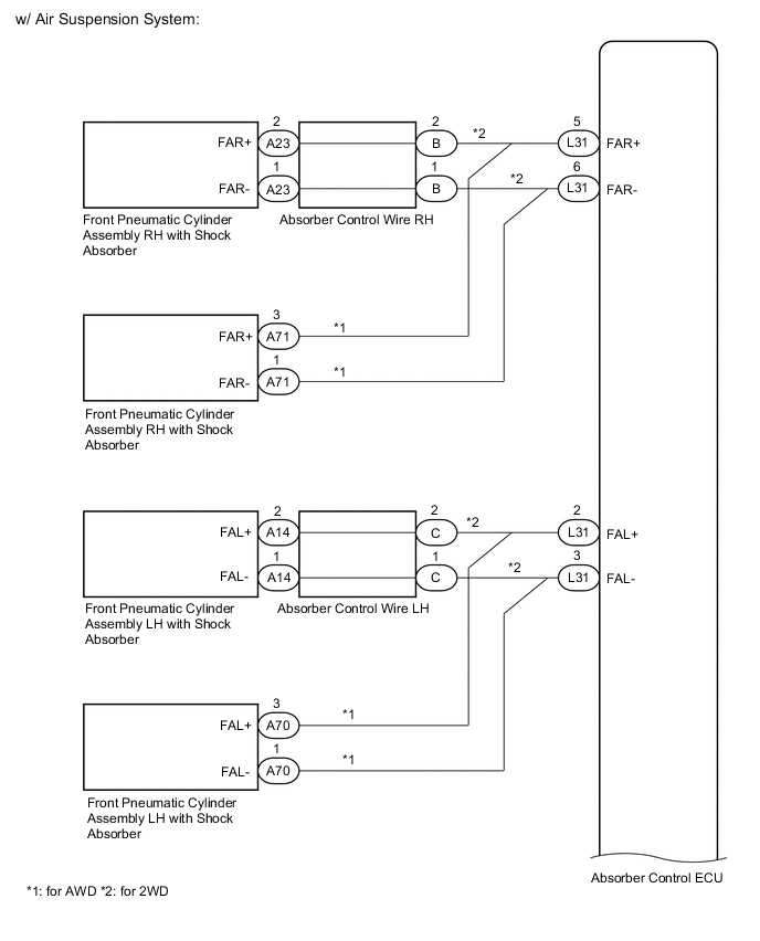
Standard Resistance Table 1. for Front RH Tester Connection Condition Specified Condition L46-5 (FAR+) - A71-3 (FAR+) Always Below 1 Ω L46-6 (FAR-) - A71-1 (FAR-) L46-5 (FAR+) or A71-3 (FAR+) - Body ground Always 10 kΩ or higher L46-6 (FAR-) or A71-1 (FAR-) - Body ground Table 2. for Front LH Tester Connection Condition Specified Condition L46-2 (FAL+) - A70-3 (FAL+) Always Below 1 Ω L46-3 (FAL-) - A70-1 (FAL-) L46-2 (FAL+) or A70-3 (FAL+) - Body ground Always 10 kΩ or higher L46-3 (FAL-) or A70-1 (FAL-) - Body ground Result Proceed to OK NG
- OK
REPLACE ABSORBER CONTROL ECUClick here
- NG
REPAIR OR REPLACE HARNESS OR CONNECTOR
-
- Click here
CHECK HARNESS AND CONNECTOR (FRONT SHOCK ABSORBER ASSEMBLY - ABSORBER CONTROL ECU)
-
Turn the power switch off.
-
Disconnect the L46 absorber control ECU connector.
-
Disconnect the A23 or A14 absorber control wire connector.
-
Measure the resistance according to the value(s) in the table below.
Standard Resistance Table 3. for Front RH Tester Connection Condition Specified Condition L46-5 (FAR+) - A23-2 (FAR+) Always Below 1 Ω L46-6 (FAR-) - A23-1 (FAR-) L46-5 (FAR+) or A23-2 (FAR+) - Body ground Always 10 kΩ or higher L46-6 (FAR-) or A23-1 (FAR-) - Body ground Table 4. for Front LH Tester Connection Condition Specified Condition L46-2 (FAL+) - A14-2 (FAL+) Always Below 1 Ω L46-3 (FAL-) - A14-1 (FAL-) L46-2 (FAL+) or A14-2 (FAL+) - Body ground Always 10 kΩ or higher L46-3 (FAL-) or A14-1 (FAL-) - Body ground Result Proceed to OK NG
- OK
REPLACE ABSORBER CONTROL ECUClick here
- NGClick here
-
- Click here
INSPECT ABSORBER CONTROL WIRE
-
Turn the power switch off.
-
Disconnect the B or C absorber control wire connector.
-
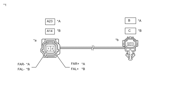
*A RH *B LH *1 Absorber Control Wire - - *a Front view of wire harness connector
(to Front Absorber Control Actuator Side Connector)
*b Front view of wire harness connector
(to Vehicle Side Connector)
Measure the resistance according to the value(s) in the table below.
Standard Resistance Table 5. for RH Tester Connection Condition Specified Condition B -1 - A23 -1 (FAR-) Always Below 1 Ω B -2 - A23 -2 (FAR+) B -1 or A23 -1 (FAR-) - Body ground and other terminals Always 10 kΩ or higher B -2 or A23 -2 (FAR+) - Body ground and other terminals Standard Resistance Table 6. for LH Tester Connection Condition Specified Condition C -1 - A14 -1 (FAL-) Always Below 1 Ω C -2 - A14 -2 (FAL+) C -1 or A14 -1 (FAL-) - Body ground and other terminals Always 10 kΩ or higher C -2 or A14 -2 (FAL+) - Body ground and other terminals Result Proceed to OK NG
- OK
REPAIR OR REPLACE HARNESS OR CONNECTOR
- NG
REPLACE ABSORBER CONTROL WIREClick here
-
- Click here
CHECK HARNESS AND CONNECTOR (REAR SHOCK ABSORBER ASSEMBLY - ABSORBER CONTROL ECU)
-
Turn the power switch off.
-
Disconnect the L45 or D skid control sensor wire connector.
-
Measure the resistance according to the value(s) in the table below.
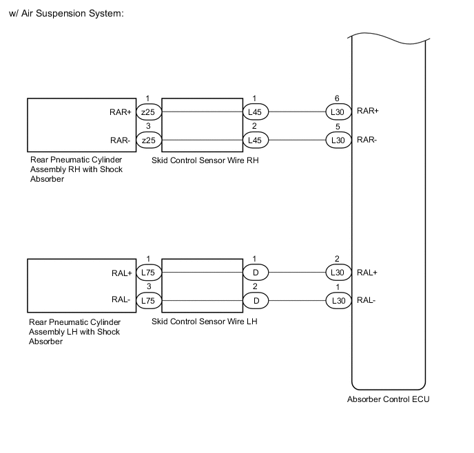
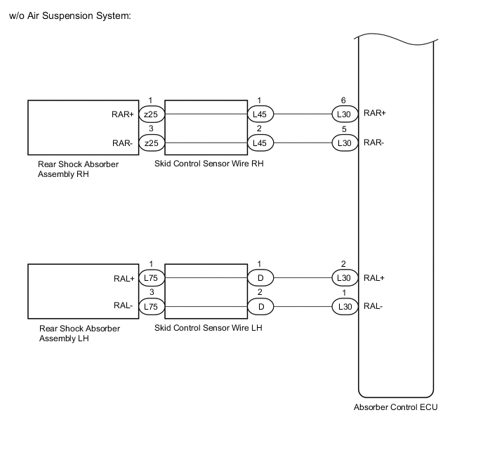
Standard Resistance Table 7. for Rear RH Tester Connection Condition Specified Condition L30-6 (RAR+) - z25-1 (RAR+) Always Below 1 Ω L30-5 (RAR-) - z25-3 (RAR-) L30-6 (RAR+) or z25-1 (RAR+) - Body ground Always 10 kΩ or higher L30-5 (RAR-) or z25-3 (RAR-) - Body ground Table 8. for Rear LH Tester Connection Condition Specified Condition L30-2 (RAL+) - L75-1 (RAL+) Always Below 1 Ω L30-1 (RAL-) - L75-3 (RAL-) L30-2 (RAL+) or L75-1 (RAL+) - Body ground Always 10 kΩ or higher L30-1 (RAL-) or L75-3 (RAL-) - Body ground Result Proceed to OK NG
- OK
REPLACE ABSORBER CONTROL ECUClick here
- NGClick here
-
- Click here
INSPECT SKID CONTROL SENSOR WIRE
-
Turn the power switch off.
-
Disconnect the z25 or L75 skid control sensor wire connector.
-
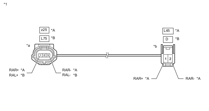
*A RH *B LH *1 Skid Control Sensor Wire - - *a Front view of wire harness connector
(to Rear Absorber Control Actuator Side Connector)
*b Front view of wire harness connector
(to Vehicle Side Connector)
Measure the resistance according to the value(s) in the table below.
Standard Resistance Table 9. for RH Tester Connection Condition Specified Condition L45 -1 - z25 -1 (RAR+) Always Below 1 Ω L45 -2 - z25 -3 (RAR-) L45 -1 or z25 -1 (RAR+) - Body ground and other terminals Always 10 kΩ or higher L45 -2 or z25 -3 (RAR-) - Body ground and other terminals Standard Resistance Table 10. for LH Tester Connection Condition Specified Condition D -1 - L75 -1 (RAL+) Always Below 1 Ω D -2 - L75 -3 (RAL-) D -1 or L75 -1 (RAL+) - Body ground and other terminals Always 10 kΩ or higher D -2 or L75 -3 (RAL-) - Body ground and other terminals Result Proceed to OK NG
- OK
REPAIR OR REPLACE HARNESS OR CONNECTOR
- NG
REPLACE SKID CONTROL SENSOR WIREClick here
-
- Click here
INSPECT PNEUMATIC CYLINDER ASSEMBLY WITH SHOCK ABSORBER
-
Turn the power switch off.
-
Inspect the pneumatic cylinder assembly with shock absorber.
for Front Side:Click here
for Rear Side:Click here
Result Result Proceed to OK (for Front Side) (for AWD) A OK (for Front Side) (for 2WD) B OK (for Rear Side) C Front pneumatic cylinder assembly RH with shock absorber malfunction D Front pneumatic cylinder assembly LH with shock absorber malfunction E Rear pneumatic cylinder assembly RH with shock absorber malfunction F Rear pneumatic cylinder assembly LH with shock absorber malfunction G
- AClick here
- BClick here
- CClick here
- D
REPLACE FRONT PNEUMATIC CYLINDER ASSEMBLY RH WITH SHOCK ABSORBER for 2WD:Click here
REPLACE FRONT PNEUMATIC CYLINDER ASSEMBLY RH WITH SHOCK ABSORBER for AWD:Click here
- E
REPLACE FRONT PNEUMATIC CYLINDER ASSEMBLY LH WITH SHOCK ABSORBER for 2WD:Click here
REPLACE FRONT PNEUMATIC CYLINDER ASSEMBLY LH WITH SHOCK ABSORBER for AWD:Click here
- F
REPLACE REAR PNEUMATIC CYLINDER ASSEMBLY RH WITH SHOCK ABSORBERClick here
- G
REPLACE REAR PNEUMATIC CYLINDER ASSEMBLY LH WITH SHOCK ABSORBERClick here
-
- Click here
CHECK HARNESS AND CONNECTOR (FRONT PNEUMATIC CYLINDER ASSEMBLY WITH SHOCK ABSORBER - ABSORBER CONTROL ECU)
-
Turn the power switch off.
-
Disconnect the L46 absorber control ECU connector.
-
Disconnect the A71 or A70 absorber control wire connector.
-
Measure the resistance according to the value(s) in the table below.
Standard Resistance Table 11. for Front RH Tester Connection Condition Specified Condition L46-5 (FAR+) - A71-3 (FAR+) Always Below 1 Ω L46-6 (FAR-) - A71-1 (FAR-) L46-5 (FAR+) or A71-3 (FAR+) - Body ground Always 10 kΩ or higher L46-6 (FAR-) or A71-1 (FAR-) - Body ground Table 12. for Front LH Tester Connection Condition Specified Condition L46-2 (FAL+) - A70-3 (FAL+) Always Below 1 Ω L46-3 (FAL-) - A70-1 (FAL-) L46-2 (FAL+) or A70-3 (FAL+) - Body ground Always 10 kΩ or higher L46-3 (FAL-) or A70-1 (FAL-) - Body ground Result Proceed to OK NG
- OK
REPLACE ABSORBER CONTROL ECU Click here
- NG
REPAIR OR REPLACE HARNESS OR CONNECTOR
-
- Click here
CHECK HARNESS AND CONNECTOR (FRONT PNEUMATIC CYLINDER ASSEMBLY WITH SHOCK ABSORBER - ABSORBER CONTROL ECU)
-
Turn the power switch off.
-
Disconnect the L46 absorber control ECU connector.
-
Disconnect the A23 or A14 absorber control wire connector.
-
Measure the resistance according to the value(s) in the table below.
Standard Resistance Table 13. for Front RH Tester Connection Condition Specified Condition L46-5 (FAR+) - A23-2 (FAR+) Always Below 1 Ω L46-6 (FAR-) - A23-1 (FAR-) L46-5 (FAR+) or A23-2 (FAR+) - Body ground Always 10 kΩ or higher L46-6 (FAR-) or A23-1 (FAR-) - Body ground Table 14. for Front LH Tester Connection Condition Specified Condition L46-2 (FAL+) - A14-2 (FAL+) Always Below 1 Ω L46-3 (FAL-) - A14-1 (FAL-) L46-2 (FAL+) or A14-2 (FAL+) - Body ground Always 10 kΩ or higher L46-3 (FAL-) or A14-1 (FAL-) - Body ground Result Proceed to OK NG
- OK
REPLACE ABSORBER CONTROL ECUClick here
- NGClick here
-
- Click here
INSPECT ABSORBER CONTROL WIRE
-
Turn the power switch off.
-
Disconnect the B or C absorber control wire connector.
-
*A RH *B LH *1 Absorber Control Wire - - *a Front view of wire harness connector
(to Front Absorber Control Actuator Side Connector)
*b Front view of wire harness connector
(to Vehicle Side Connector)
Measure the resistance according to the value(s) in the table below.
Standard Resistance Table 15. for RH Tester Connection Condition Specified Condition B -1 - A23 -1 (FAR-) Always Below 1 Ω B -2 - A23 -2 (FAR+) B -1 or A23 -1 (FAR-) - Body ground and other terminals Always 10 kΩ or higher B -2 or A23 -2 (FAR+) - Body ground and other terminals Standard Resistance Table 16. for LH Tester Connection Condition Specified Condition C-1 - A14 -1 (FAL-) Always Below 1 Ω C -2 - A14 -2 (FAL+) C -1 or A14 -1 (FAL-) - Body ground and other terminals Always 10 kΩ or higher C -2 or A14 -2 (FAL+) - Body ground and other terminals Result Proceed to OK NG
- OK
REPAIR OR REPLACE HARNESS OR CONNECTOR
- NG
REPLACE ABSORBER CONTROL WIREClick here
-
- Click here
CHECK HARNESS AND CONNECTOR (REAR PNEUMATIC CYLINDER ASSEMBLY WITH SHOCK ABSORBER - ABSORBER CONTROL)
-
Turn the power switch off.
-
Disconnect the L45 or D skid control sensor wire connector.
-
Measure the resistance according to the value(s) in the table below.
Standard Resistance Table 17. for Rear RH Tester Connection Condition Specified Condition L30-6 (RAR+) - z25-1 (RAR+) Always Below 1 Ω L30-5 (RAR-) - z25-3 (RAR-) L30-6 (RAR+) or z25-1 (RAR+) - Body ground Always 10 kΩ or higher L30-5 (RAR-) or z25-3 (RAR-) - Body ground Table 18. for Rear LH Tester Connection Condition Specified Condition L30-2 (RAL+) - L75-1 (RAL+) Always Below 1 Ω L30-1 (RAL-) - L75-3 (RAL-) L30-2 (RAL+) or L75-1 (RAL+) - Body ground Always 10 kΩ or higher L30-1 (RAL-) or L75-3 (RAL-) - Body ground Result Proceed to OK NG
- OK
REPLACE ABSORBER CONTROL ECUClick here
- NGClick here
-
- Click here
INSPECT SKID CONTROL SENSOR WIRE
-
Turn the power switch off.
-
Disconnect the z25 or L75 skid control sensor wire connector.
-
*A RH *B LH *1 Skid Control Sensor Wire - - *a Front view of wire harness connector
(to Rear Absorber Control Actuator Side Connector)
*b Front view of wire harness connector
(to Vehicle Side Connector)
Measure the resistance according to the value(s) in the table below.
Standard Resistance Table 19. for RH Tester Connection Condition Specified Condition L45 -1 - z25 -1 (RAR+) Always Below 1 Ω L45 -2 - z25 -3 (RAR-) L45 -1 or z25 -1 (RAR+) - Body ground and other terminals Always 10 kΩ or higher L45 -2 or z25 -3 (RAR-) - Body ground and other terminals Standard Resistance Table 20. for LH Tester Connection Condition Specified Condition D -1 - L75 -1 (RAL+) Always Below 1 Ω D -2 - L75 -3 (RAL-) D -1 or L75 -1 (RAL+) - Body ground and other terminals Always 10 kΩ or higher D -2 or L75 -3 (RAL-) - Body ground and other terminals Result Proceed to OK NG
- OK
REPAIR OR REPLACE HARNESS OR CONNECTOR
- NG
REPLACE SKID CONTROL SENSOR WIREClick here
-