LIGHTING SYSTEM Rear Fog Light Circuit
DESCRIPTION
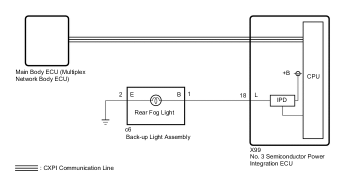
The main body ECU (multiplex network body ECU) controls the rear fog light.
WIRING DIAGRAM
CAUTION / NOTICE / HINT
Note
-
Inspect the bulb for circuits related to this system before performing the following procedure.
-
Before replacing the main body ECU (multiplex network body ECU), refer to Service Bulletin.
-
First perform the communication function inspections in How to Proceed with Troubleshooting to confirm that there are no CXPI communication malfunctions before troubleshooting this symptom.
-
First, confirm that there is no malfunction in the power integration system. Refer to the How to Proceed with Troubleshooting procedure.
-
After turning the power switch off, waiting time may be required before disconnecting the cable from the negative (-) auxiliary battery terminal. Therefore, make sure to read the disconnecting the cable from the negative (-) auxiliary battery terminal notices before proceeding with work.
-
When disconnecting the cable from the negative (-) auxiliary battery terminal while performing repairs, some systems need to be initialized after the cable is reconnected.
PROCEDURE
-
READ VALUE USING GTS
-
Turn the rear fog light switch on.
-
Using the GTS, read the Data List.
Body Electrical > Power Integration No.3 > Data ListTester Display Measurement Item Range Normal Condition Diagnostic Note Status of Rear Fog Light Fuse Rear fog light fuse Connect or Disconnect Connect: Fuse not shut off
Disconnect: Fuse shut off
-
Body Electrical > Power Integration No.3 > Data ListTester Display Status of Rear Fog Light Fuse OK The Data List value displays "Connect". Result Proceed to OK NG
NG 
CHECK BACK-UP LIGHT ASSEMBLY Click here
OK 
-
-
READ VALUE USING GTS
-
Using the GTS, read the Data List.
Body Electrical > Power Integration No.3 > Data ListTester Display Measurement Item Range Normal Condition Diagnostic Note Rear Fog Light Input Signal Rear fog light switch input signal OFF or ON OFF: Rear fog light switch off
ON: Rear fog light switch on
-
Body Electrical > Power Integration No.3 > Data ListTester Display Rear Fog Light Input Signal OK Display changes according to the rear fog light switch operation. Result Proceed to OK NG
NG 
REPLACE MAIN BODY ECU (MULTIPLEX NETWORK BODY ECU) Click here
OK
-
-
READ VALUE USING GTS
-
Using the GTS, read the Data List.
Body Electrical > Power Integration No.3 > Data ListTester Display Measurement Item Range Normal Condition Diagnostic Note Rear Fog Light Output Signal Rear fog light output condition OFF or ON OFF: Rear fog light not illuminated
ON: Rear fog light illuminated
-
Body Electrical > Power Integration No.3 > Data ListTester Display Rear Fog Light Output Signal OK Display changes according to the rear fog light switch operation. Result Proceed to OK NG
NG
REPLACE NO. 3 SEMICONDUCTOR POWER INTEGRATION ECU Click here
OK
-
-
INSPECT BACK-UP LIGHT ASSEMBLY
-
Remove the back-up light assembly connector.
-
Apply auxiliary battery voltage to the connector and check the illumination conditions.
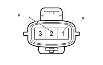
OK Auxiliary Battery Connection Specified Condition Positive (+) → 1 (B)
Negative (-) → 2 (E)
Rear fog light illuminates Result Proceed to OK NG
NG
REPLACE BACK-UP LIGHT ASSEMBLY Click here
OK
-
-
CHECK HARNESS AND CONNECTOR (BACK-UP LIGHT ASSEMBLY - NO. 3 SEMICONDUCTOR POWER INTEGRATION ECU AND BODY GROUND)
-
Disconnect the c6 back-up light assembly connector.
-
Disconnect the cable from the negative (-) auxiliary battery terminal.
-
Disconnect the X99 No. 3 semiconductor power integration ECU connector.
-
Measure the resistance according to the value(s) in the table below.
Standard Resistance Tester Connection Condition Specified Condition c6-1 (B) - X99-18 (L) Always Below 1 Ω c6-2 (E) - Body ground Always Below 1 Ω -
Connect the cable to the negative (-) auxiliary battery terminal.
Note
When disconnecting the cable, some systems need to be initialized after the cable is reconnected.
-
Measure the voltage according to the value(s) in the table below.
Standard Voltage Tester Connection Condition Specified Condition c6-1 (B) or X99-18 (L) - Body ground Always Below 1 V Result Proceed to OK NG
OK
REPLACE NO. 3 SEMICONDUCTOR POWER INTEGRATION ECU Click here
NG
REPAIR OR REPLACE HARNESS OR CONNECTOR
-
-
CHECK BACK-UP LIGHT ASSEMBLY
-
Disconnect the c6 back-up light assembly connector.
-
Turn the rear fog light switch off.
-
Turn the rear fog light switch on.
-
Using the GTS, read the Data List.
Body Electrical > Power Integration No.3 > Data ListTester Display Measurement Item Range Normal Condition Diagnostic Note Status of Rear Fog Light Fuse Rear fog light fuse Connect or Disconnect Connect: Fuse not shut off
Disconnect: Fuse shut off
-
Body Electrical > Power Integration No.3 > Data ListTester Display Status of Rear Fog Light Fuse OK The Data List value displays "Connect". Result Proceed to OK NG
OK
REPLACE BACK-UP LIGHT ASSEMBLY Click here
NG
-
-
CHECK HARNESS AND CONNECTOR (BACK-UP LIGHT ASSEMBLY - NO. 3 SEMICONDUCTOR POWER INTEGRATION ECU)
-
Disconnect the c6 back-up light assembly connector.
-
Disconnect the cable from the negative (-) auxiliary battery terminal.
-
Disconnect the X99 No. 3 semiconductor power integration ECU connector.
-
Measure the resistance according to the value(s) in the table below.
Standard Resistance Tester Connection Condition Specified Condition c6-1 (B) or X99-18 (L) - Body ground Always 10 kΩ or higher Result Proceed to OK NG
OK
REPLACE NO. 3 SEMICONDUCTOR POWER INTEGRATION ECU Click here
NG
REPAIR OR REPLACE HARNESS OR CONNECTOR
-