STOP LIGHT SWITCH REMOVAL
CAUTION / NOTICE / HINT
for LHD:
The necessary procedures (adjustment, calibration, initialization, or registration) that must be performed after parts are removed, installed, or replaced during the stop light switch assembly removal/installation are shown below.
| Replacement Part or Procedure | Necessary Procedure | Effect/Inoperative when not Performed | Link |
|---|---|---|---|
| Disconnect cable from negative(-) auxiliary battery terminal | Memorize steering angle neutral point | LKA/LDA system | |
| Pre-collision system | |||
| Initialize parking assist monitor system | Parking assist monitor system | ||
| Steering Sensor Initialization | Variable gear ratio steering system |
Tech Tips
-
Use the same procedure for RHD and LHD vehicles.
-
The procedure listed below is for LHD vehicles.
PROCEDURE
-
REMOVE NO. 2 DECK BOARD (for LHD)
-
PRECAUTION (for LHD)
Note
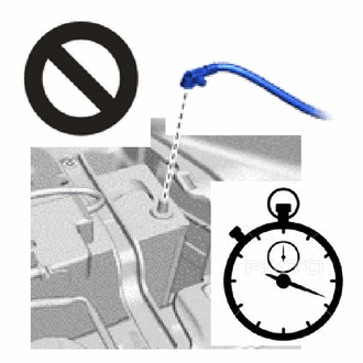
After turning the power switch off, waiting time may be required before disconnecting the cable from the negative(-) auxiliary battery terminal. Therefore, make sure to read the disconnecting the cable from the negative(-) auxiliary battery terminal notices before proceeding with work.
-
DISCONNECT CABLE FROM NEGATIVE AUXILIARY BATTERY TERMINAL (for LHD)
CAUTION:
-
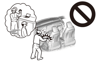
Wait at least 90 seconds after disconnecting the cable from the negative(-) auxiliary battery terminal to disable the SRS system.
-
If the airbag deploys for any reason, it may cause a serious accident.
Note
When disconnecting the cable, some systems need to be initialized after the cable is reconnected.
-
-
REMOVE DRIVER SIDE JUNCTION BLOCK ASSEMBLY WITH MAIN BODY ECU (for LHD)
-
REMOVE NO. 1 INSTRUMENT PANEL UNDER COVER SUB-ASSEMBLY (for RHD)
-
REMOVE STOP LIGHT SWITCH ASSEMBLY
-
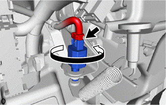
Disconnect the connector.
-
Turn the stop light switch assembly counterclockwise and remove it.
-
-
REMOVE STOP LIGHT SWITCH MOUNTING ADJUSTER
-
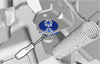

Protective Tape Using a screwdriver, detach the claw and remove the stop light switch mounting adjuster.
Note
The stop light switch mounting adjuster must not be reused.
Tech Tips
Tape the screwdriver tip before use.
-