WASHER MOTOR REMOVAL
CAUTION / NOTICE / HINT
The necessary procedures (adjustment, calibration, initialization, or registration) that must be performed after parts are removed, installed, or replaced during the washer jar assembly removal/installation are shown below.
| Replacement Part or Procedure | Necessary Procedure | Effect/Inoperative when not Performed | Link |
|---|---|---|---|
| Disconnect cable from negative auxiliary battery terminal | Memorize steering angle neutral point | LKA/LDA system | |
| Pre-collision system | |||
| Parking assist monitor system | |||
| Steering sensor zero point calibration | Variable gear ratio steering system |
PROCEDURE
-
PRECAUTION
Note
After turning the power switch off, waiting time may be required before disconnecting the cable from the negative (-) auxiliary battery terminal. Therefore, make sure to read the disconnecting the cable from the negative (-) auxiliary battery terminal notices before proceeding with work.
-
REMOVE NO. 2 DECK BOARD
-
DISCONNECT CABLE FROM NEGATIVE AUXILIARY BATTERY TERMINAL
CAUTION:
-
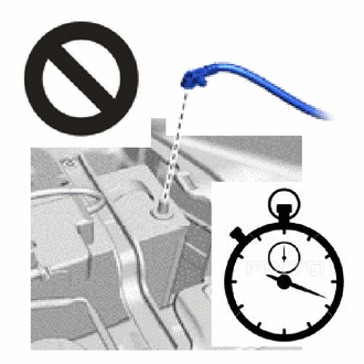
Wait at least 90 seconds after disconnecting the cable from the negative(-) auxiliary battery terminal to disable the SRS system.
-
If the airbag deploys for any reason, it may cause a serious accident.
Note
When disconnecting the cable, some systems need to be initialized after the cable is reconnected.
-
-
REMOVE FRONT WHEEL LH
-
REMOVE NO. 1 ENGINE UNDER COVER ASSEMBLY
-
REMOVE NO. 2 ENGINE UNDER COVER ASSEMBLY
-
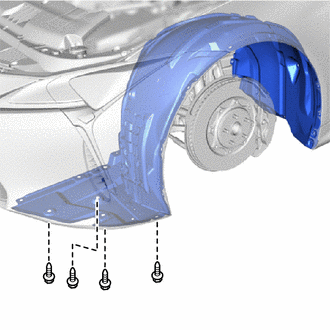
REMOVE FRONT WHEEL OPENING EXTENSION PAD LH
-
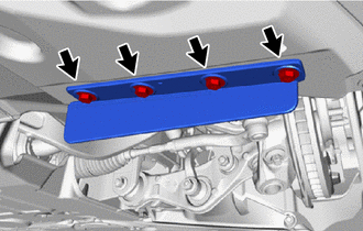
Remove the 4 screws and front wheel opening extension pad LH.
-
-
REMOVE ENGINE SIDE COVER LH
-
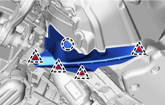
Remove the 4 clips.
-
Detach the claw and remove the engine side cover LH.
-
-
REMOVE FRONT FENDER LINER LH
-
Remove the 4 screws.
-
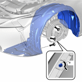
*a 90° Using a screwdriver, turn the 3 pin hold clips 90° and remove them.
-
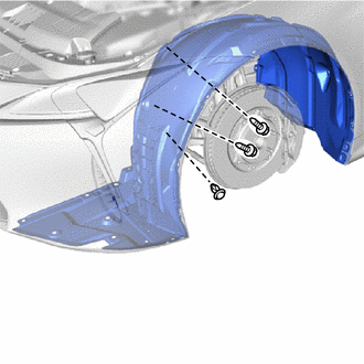
Remove the 2 screws and clip.
-
Remove the 3 clips.
-
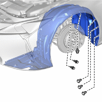
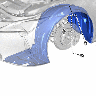
Remove the 6 clips.
-
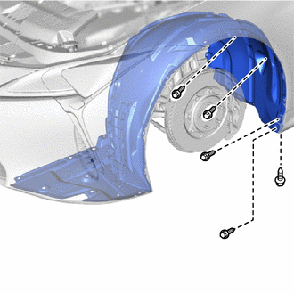
Remove the 5 screws.
-
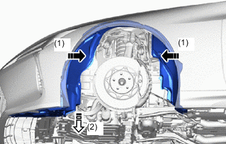

Remove in this Direction (1) 
Remove in this Direction (2) Bend the front fender liner LH inward and remove it while sliding the duct towards the bottom of the vehicle as shown in the illustration.
-
-
DRAIN WINDSHIELD WASHER FLUID
-
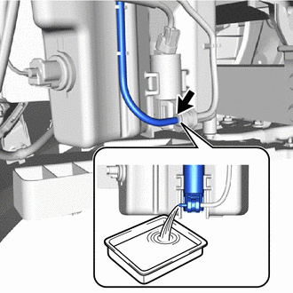
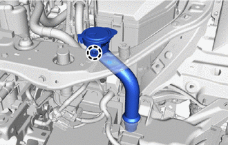
Disconnect the washer hose and drain the windshield washer fluid.
Tech Tips
Prepare a container before performing the procedure.
-
-
REMOVE WINDSHIELD WASHER MOTOR AND PUMP ASSEMBLY
-
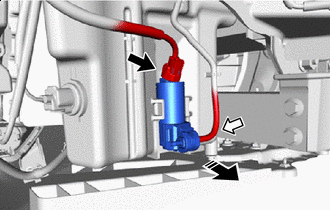
Remove in this Direction Disconnect the connector.
-
Disconnect the washer hose.
-
Pull in the direction of the arrow shown in the illustration and remove the windshield washer motor and pump assembly.
-
Remove the grommet.
-
-
REMOVE FRONT BUMPER COVER
-
REMOVE HEADLIGHT CLEANER HOSE
-
REMOVE NO. 2 FRONT BUMPER MOUNTING BRACKET
-
REMOVE PEDESTRIAN DETECTION CHAMBER ASSEMBLY
-
REMOVE FRONT BUMPER ENERGY ABSORBER
-
REMOVE HEADLIGHT ASSEMBLY LH
-
REMOVE LOWER ARM BRACKET BRACE SUB-ASSEMBLY LH
-
REMOVE LOWER ARM BRACKET BRACE SUB-ASSEMBLY RH
Tech Tips
Use the same procedure described for the LH side
-
REMOVE FRONT BUMPER REINFORCEMENT SUB-ASSEMBLY
-
REMOVE WASHER INLET SUB-ASSEMBLY
-
Detach the claw and remove the washer inlet sub-assembly.
-
-
REMOVE WINDSHIELD WASHER JAR ASSEMBLY
-
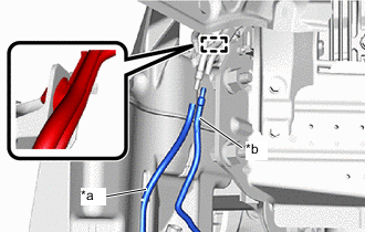
*a Main Nozzle Side *b Sub Nozzle Side Disconnect the clamp and washer hose at the position shown in the illustration.
-
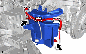
Disconnect the 2 connectors and clamps.
-
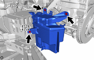
Remove the 3 bolts, detach the guide and remove the windshield washer jar assembly.
-
-
REMOVE LEVEL WARNING SWITCH ASSEMBLY
-
REMOVE HEADLIGHT CLEANER MOTOR AND PUMP ASSEMBLY
-
REMOVE HEADLIGHT CLEANER CONTROL RELAY