POWER MIRROR CONTROL SYSTEM Front Passenger Side Power Mirror cannot be Adjusted with Power Mirror Switch
DESCRIPTION
The multiplex network master switch assembly sends the mirror adjust switch signals to the main body ECU (multiplex network body ECU) via LIN communication. The main body ECU (multiplex network body ECU) then sends the received mirror adjust switch signals to the front multiplex network door ECU (front passenger door) via CAN communication. Upon receiving the signal, the front multiplex network door ECU (front passenger door) operates the vertical and horizontal mirror motors, which are built into the outer mirror actuator assembly (front passenger door), to adjust the mirror surface position.
WIRING DIAGRAM
Figure 1. for LHD:
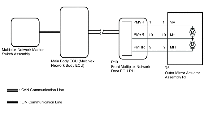
Figure 2. for RHD:

CAUTION / NOTICE / HINT
Note
-
The power mirror control system uses the CAN communication system and LIN communication system. Inspect the communication functions by following How to Proceed with Troubleshooting. Troubleshoot the power window control system after confirming that the communication systems are functioning properly.
-
Before replacing the main body ECU (multiplex network body ECU), refer to Service Bulletin.
PROCEDURE
-
READ VALUE USING GTS (MIRROR SELECTION SW (L/R), MIRROR POSITION SW (L/R/UP/DWN))
-
Connect the GTS to the DLC3.
-
Turn the power switch on (IG).
-
Turn the GTS on.
-
Enter the following menus: Body Electrical / Master Switch / Data List.
-
Read the Data List according to the display on the GTS.
Body Electrical > Master Switch > Data ListTester Display Measurement Item Range Normal Condition Diagnostic Note Mirror Selection SW (L) Mirror select switch signal for LH mirror OFF or ON OFF: Mirror select switch off
ON: Mirror select switch L switch on
for RHD Mirror Selection SW (R) Mirror select switch signal for RH mirror OFF or ON OFF: Mirror select switch off
ON: Mirror select switch R switch on
for LHD Mirror Position SW (L) Mirror adjust switch signal (Left) OFF or ON OFF: Mirror adjust switch not pressed left
ON: Mirror adjust switch pressed left
Check with the mirror select switch L or R switch on Mirror Position SW (R) Mirror adjust switch signal (Right) OFF or ON OFF: Mirror adjust switch not pressed right
ON: Mirror adjust switch pressed right
Check with the mirror select switch L or R switch on Mirror Position SW (Up) Mirror adjust switch signal (Up) OFF or ON OFF: Mirror adjust switch not pressed up
ON: Mirror adjust switch pressed up
Check with the mirror select switch L or R switch on Mirror Position SW (Dwn) Mirror adjust switch signal (Down) OFF or ON OFF: Mirror adjust switch not pressed down
ON: Mirror adjust switch pressed down
Check with the mirror select switch L or R switch on
Body Electrical > Master Switch > Data ListTester Display Mirror Selection SW (L) Mirror Selection SW (R) Mirror Position SW (L) Mirror Position SW (R) Mirror Position SW (Up) Mirror Position SW (Dwn) OK On the GTS screen, ON or OFF is displayed accordingly. Result Proceed to OK NG
NG 
REPLACE MULTIPLEX NETWORK MASTER SWITCH ASSEMBLY Click here
OK 
-
-
INSPECT OUTER MIRROR ACTUATOR ASSEMBLY (FRONT PASSENGER DOOR) (MIRROR SURFACE)
-
Remove the outer mirror actuator assembly (front passenger door).
-
Inspect the outer mirror actuator assembly (front passenger door) (mirror surface).
Result Proceed to OK NG
NG 
REPLACE OUTER MIRROR ACTUATOR ASSEMBLY (FRONT PASSENGER DOOR) Click here
OK
-
-
CHECK HARNESS AND CONNECTOR (OUTER MIRROR ACTUATOR ASSEMBLY (FRONT PASSENGER DOOR) - FRONT MULTIPLEX NETWORK DOOR ECU (FRONT PASSENGER DOOR))
-
for LHD:
-
Disconnect the R6 outer mirror actuator assembly RH connector.
-
Disconnect the R10 front multiplex network door ECU RH connector.
-
Measure the resistance according to the value(s) in the table below.
Standard Resistance Tester Connection Condition Specified Condition R6-9 (MH) - R10-9 (PMHR) Always Below 1 Ω R6-9 (MH) or R10-9 (PMHR) - Body ground Always 10 kΩ or higher R6-10 (M+) - R10-10 (PM+R) Always Below 1 Ω R6-10 (M+) or R10-10 (PM+R) - Body ground Always 10 kΩ or higher R6-1 (MV) - R10-1 (PMVR) Always Below 1 Ω R6-1 (MV) or R10-1 (PMVR) - Body ground Always 10 kΩ or higher
-
-
for RHD:
-
Disconnect the S6 outer mirror actuator assembly LH connector.
-
Disconnect the S10 front multiplex network door ECU LH connector.
-
Measure the resistance according to the value(s) in the table below.
Standard Resistance Tester Connection Condition Specified Condition S6-9 (MH) - S10-9 (DMHR) Always Below 1 Ω S6-9 (MH) or S10-9 (DMHR) - Body ground Always 10 kΩ or higher S6-10 (M+) - S10-10 (DM+R) Always Below 1 Ω S6-10 (M+) or S10-10 (DM+R) - Body ground Always 10 kΩ or higher S6-1 (MV) - S10-1 (DMVR) Always Below 1 Ω S6-1 (MV) or S10-1 (DMVR) - Body ground Always 10 kΩ or higher
Result Proceed to OK NG -
OK
REPLACE FRONT MULTIPLEX NETWORK DOOR ECU (FRONT PASSENGER DOOR) Click here
NG
REPAIR OR REPLACE HARNESS OR CONNECTOR
-
-
REPLACE MULTIPLEX NETWORK MASTER SWITCH ASSEMBLY
-
Temporarily replace the multiplex network master switch assembly with a new or known good one.
Result Proceed to NEXT
NEXT
-
-
CHECK POWER MIRROR CONTROL OPERATION
-
Check the electrical remote control mirror function.
OK Electrical remote control mirror function operates normally. Result Proceed to OK NG
OK
END (MULTIPLEX NETWORK MASTER SWITCH ASSEMBLY WAS DEFECTIVE)
NG
REPLACE MAIN BODY ECU (MULTIPLEX NETWORK BODY ECU) Click here
-