WIPER AND WASHER SYSTEM, Diagnostic DTC:B1279
| DTC Code | DTC Name |
|---|---|
| B1279 | Lost Communication with Humidity/Rain Sensor LIN |
DESCRIPTION
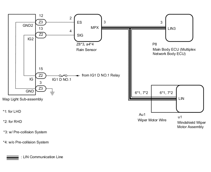
The main body ECU (multiplex network body ECU) and rain sensor communicate via LIN communication. The main body ECU (multiplex network body ECU) stores this DTC if communication becomes abnormal.
| DTC No. | Detection Item | DTC Detection Condition | Trouble Area | Memory | DTC Output from |
|---|---|---|---|---|---|
| B1279 | Lost Communication with Humidity/Rain Sensor LIN |
DTC Detection Condition:
Malfunction Status:
Malfunction Duration: |
|
○ | Main body ECU (multiplex network body ECU) |
WIRING DIAGRAM
CAUTION / NOTICE / HINT
Note
Inspect fuses for circuits related to this system before performing the following inspection procedure.
PROCEDURE
-
CHECK FOR DTC
-
Clear the DTC.
Body Electrical > Main Body > Clear DTCs -
Turn the power switch on (IG) and wait for at least 10 seconds.
-
Check for DTCs.
Body Electrical > Main Body > Trouble CodesResult Result Proceed to DTC B1279 is not output. A DTC B1279 is output. B DTC B1279 and DTC B1373 are output. C
A 
USE SIMULATION METHOD TO CHECK Click here
C
GO TO DTC B1373 Click here
B 
-
-
CHECK HARNESS AND CONNECTOR (MAIN BODY ECU [MULTIPLEX NETWORK BODY ECU] - RAIN SENSOR)
-
Disconnect the P8 main body ECU (multiplex network body ECU) connector.
-
Disconnect the Z8*1 or a4*2 rain sensor connector.
-
*1: w/ Pre-collision System
-
*2: w/o Pre-collision System
-
-
Measure the resistance according to the value(s) in the table below.
Standard Resistance w/ Pre-collision System Tester Connection Condition Specified Condition P8-3 (LIN3) - Z8-3 (MPX) Always Below 1 Ω w/o Pre-collision System Tester Connection Condition Specified Condition P8-3 (LIN3) - a4-3 (MPX) Always Below 1 Ω Result Proceed to OK NG
NG
REPAIR OR REPLACE HARNESS OR CONNECTOR
OK
-
-
CHECK HARNESS AND CONNECTOR (RAIN SENSOR - BATTERY AND BODY GROUND)
-
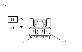
*A w/ Pre-collision System *B w/o Pre-collision System *a Front view of wire harness connector
(to Rain Sensor)
Disconnect the rain sensor connector.
-
Measure the resistance according to the value(s) in the table below.
Standard Resistance w/ Pre-collision System Tester Connection Condition Specified Condition Z8-2 (ES) - Body ground Always Below 1 Ω w/o Pre-collision System Tester Connection Condition Specified Condition a4-2 (ES) - Body ground Always Below 1 Ω -
Measure the voltage according to the value(s) in the table below.
Standard Voltage w/ Pre-collision System Tester Connection Switch Condition Specified Condition Z8-4 (SIG) - Body ground Power switch off Below 1 V Power switch on (IG) 11 to 14 V w/o Pre-collision System Tester Connection Switch Condition Specified Condition a4-4 (SIG) - Body ground Power switch off Below 1 V Power switch on (IG) 11 to 14 V Result Proceed to OK NG
OK
REPLACE RAIN SENSOR Click here
NG
-
-
INSPECT MAP LIGHT SUB-ASSEMBLY
-
Remove the map light sub-assembly.
-
Measure the resistance according to the value(s) in the table below.
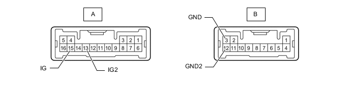
Standard Resistance Tester Connection Condition Specified Condition A-15 (IG) - A-13 (IG2) Always Below 1 Ω B-3 (GND) - B-12 (GND2) Always Below 1 Ω Result Proceed to OK NG
OK
REPAIR OR REPLACE HARNESS OR CONNECTOR
NG
REPLACE MAP LIGHT SUB-ASSEMBLY Click here
-