FLUSH HANDLE SYSTEM Only the Driver Side Flush Handle Extension or Retraction Operation does not Operate
DESCRIPTION
The signals of each switch from inside the door outside handle sub-assembly LH*1 or door outside handle sub-assembly RH*2 in the driver side flush handle are sent to the main body ECU (multiplex network body ECU) through the front multiplex network door ECU LH*1 or front multiplex network door ECU RH*2. The main body ECU (multiplex network body ECU) performs operation judgment based on input signals and sends operation request signals to the front multiplex network door ECU LH*1 or front multiplex network door ECU RH*2.
-
*1: for LHD
-
*2: for RHD
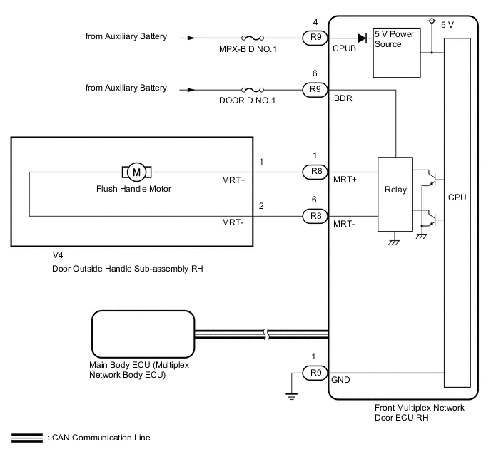
WIRING DIAGRAM
-
for LHD

-
for RHD
CAUTION / NOTICE / HINT
Note
Inspect fuses for circuits related to this system before performing the following inspection procedure.
PROCEDURE
-
CHECK VEHICLE TYPE
-
Check the vehicle type.
Result Result Proceed to for LHD A for RHD B
B 
PERFORM ACTIVE TEST USING GTS Click here
A 
-
-
PERFORM ACTIVE TEST USING GTS
-
Perform the Active Test according to the display on the GTS.
Body Electrical > Front Left Door > Active TestTester Display Measurement Item Control Range Diagnostic Note Flash Handle Return Opens door outside handle sub-assembly LH Return or OFF - Flash Handle Fold Retracts door outside handle sub-assembly LH Fold or OFF -
Body Electrical > Front Left Door > Active TestTester Display Flash Handle Return
Body Electrical > Front Left Door > Active TestTester Display Flash Handle Fold OK The door outside handle sub-assembly LH opens and retracts. Result Proceed to OK NG
OK 
REPLACE FRONT MULTIPLEX NETWORK DOOR ECU LH Click here
NG
-
-
INSPECT DOOR OUTSIDE HANDLE SUB-ASSEMBLY LH (FLUSH HANDLE MOTOR)
-
Remove the door outside handle sub-assembly LH (flush handle motor).
-
Inspect the door outside handle sub-assembly LH (flush handle motor).
Result Proceed to OK NG
NG
REPLACE DOOR OUTSIDE HANDLE SUB-ASSEMBLY LH (FLUSH HANDLE MOTOR) Click here
OK
-
-
CHECK HARNESS AND CONNECTOR (FRONT MULTIPLEX NETWORK DOOR ECU LH - BATTERY AND BODY GROUND)
-

*a Front view of wire harness connector:
(to Front Multiplex Network Door ECU LH)
Disconnect the front multiplex network door ECU LH connector.
-
Measure the resistance according to the value(s) in the table below.
Standard Resistance Tester Connection Condition Specified Condition S9-1 (GND) - Body ground Always Below 1 Ω -
Measure the voltage according to the value(s) in the table below.
Standard Voltage Tester Connection Switch Condition Specified Condition S9-4 (CPUB) - Body ground Power switch off 11 to 14 V S9-6 (BDR) - Body ground Power switch off 11 to 14 V OK Proceed to OK NG
NG
REPAIR OR REPLACE HARNESS OR CONNECTOR
OK
-
-
CHECK HARNESS AND CONNECTOR (FRONT MULTIPLEX NETWORK DOOR ECU LH - DOOR OUTSIDE HANDLE SUB-ASSEMBLY LH)
-
Disconnect the S8 front multiplex network door ECU LH connector.
-
Disconnect the W4 door outside handle sub-assembly LH connector.
-
Measure the resistance according to the value(s) in the table below.
Standard Resistance Tester Connection Condition Specified Condition S8-1 (MRT+) - W4-1 (MRT+) Always Below 1 Ω S8-6 (MRT-) - W4-2 (MRT-) Always Below 1 Ω S8-1 (MRT+) or W4-1 (MRT+) - Body ground Always 10 kΩ or higher S8-6 (MRT-) or W4-2 (MRT-) - Body ground Always 10 kΩ or higher OK Proceed to OK NG
OK
REPLACE FRONT MULTIPLEX NETWORK DOOR ECU LH Click here
NG
REPAIR OR REPLACE HARNESS OR CONNECTOR
-
-
PERFORM ACTIVE TEST USING GTS
-
Perform the Active Test according to the display on the GTS.
Body Electrical > Front Right Door > Active TestTester Display Measurement Item Control Range Diagnostic Note Flash Handle Return Opens door outside handle sub-assembly RH Return or OFF - Flash Handle Fold Retracts door outside handle sub-assembly RH Fold or OFF -
Body Electrical > Front Right Door > Active TestTester Display Flash Handle Return
Body Electrical > Front Right Door > Active TestTester Display Flash Handle Fold OK The door outside handle sub-assembly RH opens and retracts. Result Proceed to OK NG
OK
REPLACE FRONT MULTIPLEX NETWORK DOOR ECU RH Click here
NG
-
-
INSPECT DOOR OUTSIDE HANDLE SUB-ASSEMBLY RH (FLUSH HANDLE MOTOR)
-
Remove the door outside handle sub-assembly RH (flush handle motor).
-
Inspect the door outside handle sub-assembly RH (flush handle motor).
Result Proceed to OK NG
NG
REPLACE DOOR OUTSIDE HANDLE SUB-ASSEMBLY RH (FLUSH HANDLE MOTOR) Click here
OK
-
-
CHECK HARNESS AND CONNECTOR (FRONT MULTIPLEX NETWORK DOOR ECU RH - BATTERY AND BODY GROUND)
-
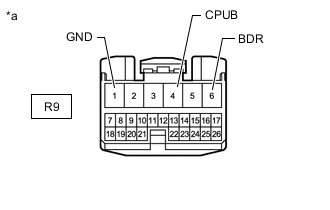
*a Front view of wire harness connector:
(to Front Multiplex Network Door ECU RH)
Disconnect the front multiplex network door ECU RH connector.
-
Measure the resistance according to the value(s) in the table below.
Standard Resistance Tester Connection Condition Specified Condition R9-1 (GND) - Body ground Always Below 1 Ω -
Measure the voltage according to the value(s) in the table below.
Standard Voltage Tester Connection Switch Condition Specified Condition R9-4 (CPUB) - Body ground Power switch off 11 to 14 V R9-6 (BDR) - Body ground Power switch off 11 to 14 V OK Proceed to OK NG
NG
REPAIR OR REPLACE HARNESS OR CONNECTOR
OK
-
-
CHECK HARNESS AND CONNECTOR (FRONT MULTIPLEX NETWORK DOOR ECU RH - DOOR OUTSIDE HANDLE SUB-ASSEMBLY RH)
-
Disconnect the R8 front multiplex network door ECU RH connector.
-
Disconnect the V4 door outside handle sub-assembly RH connector.
-
Measure the resistance according to the value(s) in the table below.
Standard Resistance Tester Connection Condition Specified Condition R8-1 (MRT+) - V4-1 (MRT+) Always Below 1 Ω R8-6 (MRT-) - V4-2 (MRT-) Always Below 1 Ω R8-1 (MRT+) or V4-1 (MRT+) - Body ground Always 10 kΩ or higher R8-6 (MRT-) or V4-2 (MRT-) - Body ground Always 10 kΩ or higher OK Proceed to OK NG
OK
REPLACE FRONT MULTIPLEX NETWORK DOOR ECU RH Click here
NG
REPAIR OR REPLACE HARNESS OR CONNECTOR
-