FRONT CONSOLE BOX REMOVAL
CAUTION / NOTICE / HINT
Tech Tips
-
Use the same procedure as for the LHD and RHD vehicles.
-
The procedure listed below is for the LHD vehicles.
PROCEDURE
-
REMOVE REAR CONSOLE BOX POCKET
-
REMOVE RADIO REMOTE TUNING SWITCH ASSEMBLY
-
REMOVE SHIFT LEVER KNOB SUB-ASSEMBLY
-
REMOVE SHIFTING HOLE COVER ASSEMBLY
-
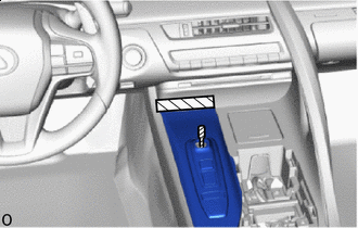

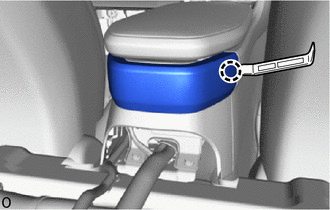
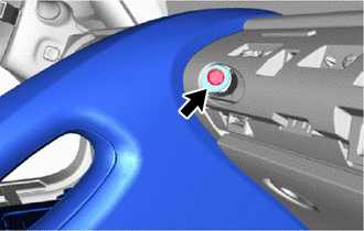
Protective Tape Apply protective tape at the position shown in the illustration.
-
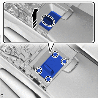
Open the lid of the console box assembly.
-

Place hand here 
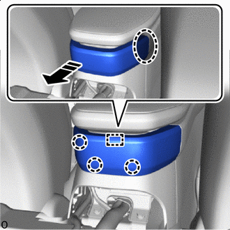
Remove in this Direction Place your hand at the position shown in the illustration and pull in the direction indicated by the arrow to detach the claws.
-
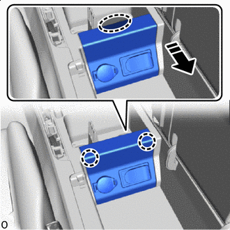
Place hand here Remove in this Direction 
Order of Removal Place your hand at the position shown in the illustration and pull in the direction indicated by the arrow and detach the claws in the order indicated by the arrow.
-
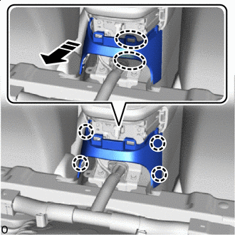
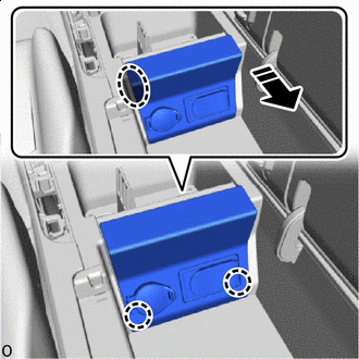
Remove in this Direction Pull out the shift lever in the direction of the arrow shown in the illustration and remove the shifting hole cover assembly.
-
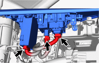
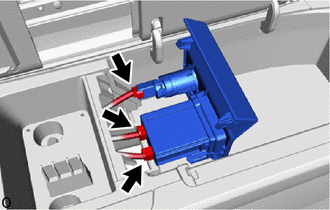
Disconnect the 3 connectors.
-
-
REMOVE REAR SEAT CUSHION ASSEMBLY
-
REMOVE REAR SEAT CUSHION LOCK HOOK
-
REMOVE UPPER CONSOLE BOX
-
Using moulding remover A, detach the claw.
-
Place hand here Remove in this Direction Place your hand in the gap in the vehicle and while pulling towards the rear of the vehicle, detach the claws and guide and remove the upper console box.
-
-
REMOVE LOWER CONSOLE BOX
-
Place hand here Remove in this Direction Place your hand at the position shown in the illustration and pull diagonally to the rear of the vehicle to detach the claws and remove the lower console box.
-
-
REMOVE EQUIPMENT SET PANEL COVER
-
Place hand here Remove in this Direction Place your hand at the position shown in the illustration and pull in the direction of the arrow to detach the claws and remove the equipment set panel cover.
-
-
REMOVE EQUIPMENT SET PANEL
-
Place hand here Remove in this Direction Place your hand at the position shown in the illustration and pull in the direction indicated by the arrow to detach the claws.
-
Place hand here Remove in this Direction Place your hand in the gap and while pulling in the direction of the arrow to detach the claws and remove the equipment set panel.
-
Disconnect the 3 connectors.
-
-
REMOVE NO. 1 GLOVE COMPARTMENT PANEL
-
REMOVE CONSOLE BOX ASSEMBLY
-
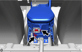
Detach the clamp and disconnect the 2 connectors.
-
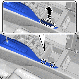
Remove the 2 bolts.
-
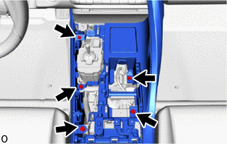
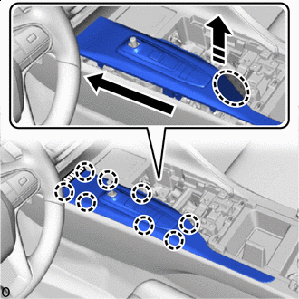
Remove the 5 bolts.
-
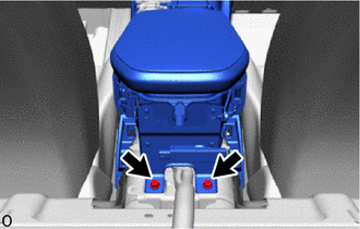
Remove the 2 bolts.
-
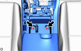
Remove the bolt.
-
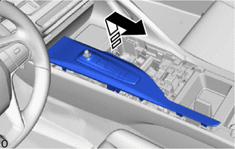
Detach the clip, claws and guides in the direction of the arrow shown in the illustration to remove the console box assembly.
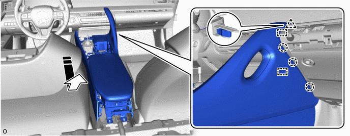
Remove in this Direction - -
-