POP UP HOOD SENSOR INSPECTION

PROCEDURE
-
INSPECT PEDESTRIAN DETECTION CHAMBER WITH PEDESTRIAN PROTECTION SENSOR
-
If B16A6 is output, any deformation caused by a hit-and-run accident, any signs of damage from hitting something lightly when parking, any airbags deployed or any defects as mentioned below, replace the front bumper energy absorber or No. 2 front bumper mounting bracket with a new one.
-
Front bumper energy absorber:
-
No. 2 front bumper mounting bracket:
Standard Front bumper energy absorber has bends or cracks No. 2 front bumper mounting bracket has bends, cracks, whitening or impact marks
-
Perform an air tightness check on the pedestrian detection chamber assembly.
-
-
-
AIR TIGHTNESS CHECK
Note
Do not remove the pedestrian detection chamber and pedestrian protection sensor.
-
Remove the pedestrian detection chamber assembly.
-
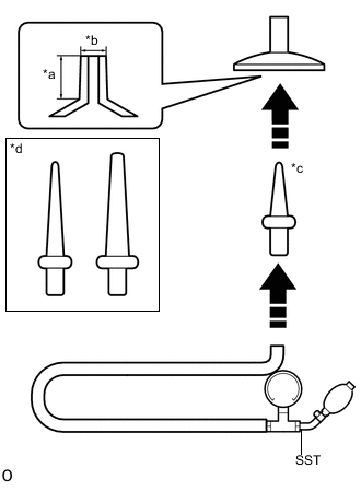
*a 12 mm (0.472 in.) *b 7 mm (0.276 in.) *c Use *d Not Use Connect the attachment to SST.
Note
Using attachment shown in the illustration.
-
Using the supplied attachment, connect the SST to the breathing hole on the other side of the sensor.
Note
Check that the securely connect the SST.
-
Use your hand to cover one of the breathing holes on the pedestrian protection sensor.
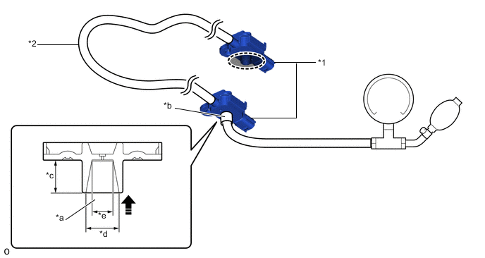
*1 Pedestrian Protection Sensor *2 Pedestrian Detection Chamber *a Attachment *b Breathing Hole *c 8.5 mm (0.335 in.) *d 8.6 mm (0.339 in.) *e 5.5 mm (0.217 in.) - - 
Cover with Hand 
Connect in this Direction -
Increase the pressure until the needle on the vacuum pump reaches 20 kPa (150 mmHg).
Tech Tips
Approximately 2 pumps are needed to increase the pressure to 20 kPa (150 mmHg).
-
Wait 10 Seconds, and check that the needle has not moved.
Tech Tips
If the needle changes, replace the pedestrian detection chamber assembly with a new one.
-