METER / GAUGE SYSTEM Hybrid System Indicator Malfunction
DESCRIPTION
A hybrid system indicator has been included on this vehicle. In this circuit, the combination meter assembly receives the eco-zone indicator level signal from the hybrid vehicle control ECU via CAN communication. The combination meter assembly controls the operation of the hybrid system indicator according to the eco-zone indicator level signal received from the hybrid vehicle control ECU via CAN communication.
WIRING DIAGRAM
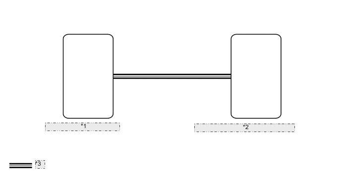
| *1 | Combination Meter Assembly |
| *2 | Hybrid Vehicle Control ECU Assembly |
| *3 | CAN Communication Line |
CAUTION / NOTICE / HINT
Note
-
Before replacing the hybrid vehicle control ECU, refer to Service Bulletin.
-
When replacing the combination meter assembly, always replace it with a new one. If a combination meter assembly which was installed to another vehicle is used, the information stored in it will not match the information from the vehicle and a DTC may be stored.
PROCEDURE
-
READ VALUE USING GTS (HV SYSTEM INDICATOR)
-
Using the GTS, perform the Active Test.
Body Electrical > Combination Meter > Data ListTester Display Measurement Item Range Normal Condition Diagnostic Note HV System Indicator Hybrid system indicator value Min.: -512%, Max.: 511% -512 to 511% -
Body Electrical > Combination Meter > Data ListTester Display HV System Indicator OK Hybrid system indicator value displayed on the GTS is almost the same as the hybrid system indicator indication. Result Proceed to OK NG
OK 
REPLACE COMBINATION METER ASSEMBLY Click here
NG 
-
-
CHECK COMBINATION METER ASSEMBLY
-
Replace the combination meter assembly.
-
Check that the operation of the hybrid system indicator returns to normal.
OK The operation of the hybrid system indicator returns to normal. Result Proceed to OK NG
OK
END (COMBINATION METER ASSEMBLY IS DEFECTIVE)
NG
REPLACE HYBRID VEHICLE CONTROL ECU Click here
-