ELECTRICAL KEY OSCILLATOR(for Front) REMOVAL
CAUTION / NOTICE / HINT
Tech Tips
-
Use the same procedure as for the RHD and LHD vehicles.
-
The procedure listed below is for the LHD vehicles.
PROCEDURE
-
REMOVE REAR CONSOLE BOX POCKET
-
REMOVE RADIO REMOTE TUNING SWITCH ASSEMBLY
-
REMOVE SHIFT LEVER KNOB SUB-ASSEMBLY
-
REMOVE SHIFTING HOLE COVER ASSEMBLY
-
REMOVE NO. 1 GLOVE COMPARTMENT PANEL
-
REMOVE UPPER CONSOLE BOX
-
REMOVE NO. 1 INDOOR ELECTRICAL KEY ANTENNA ASSEMBLY
-
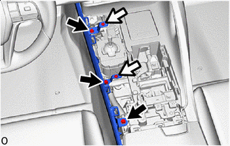

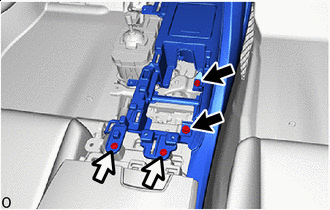
Bolt 
Screw Remove the 3 bolts and 2 screws.
-
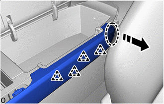

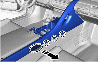
Place Hands Here 
Remove in this Direction Hold the area shown in the illustration and while pulling towards the exterior of the vehicle to detach the clips.
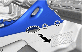
-
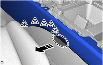
Place Hands Here Remove in this Direction Hold the area shown in the illustration and while pulling towards the exterior of the vehicle to detach the clips.
-
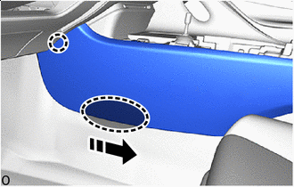
Place Hands Here Remove in this Direction Hold the area shown in the illustration, detach the claw and remove the box panel sub-assembly.
-
Bolt Screw Move the front seat (RH side) to the rearmost position and remove the 2 bolts and 2 screws.
-
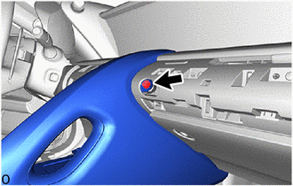
Remove the bolt.
-
Place Hands Here Remove in this Direction Fold the front seatback (RH side) forward, hold the area shown in the illustration and while pulling towards the exterior of the vehicle detach the clips and claws.
-
Place Hands Here Remove in this Direction Hold the area shown in the illustration while pulling it towards, the rear of the vehicle, detach the clip and claws and then pull out the guides from the instrument panel.
-
Place Hands Here Remove in this Direction Return the front seatback (RH side) to the original position, hold the area shown in the illustration and while pulling towards the exterior of the vehicle detach the claws.
-
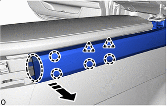
Place Hands Here Remove in this Direction Hold the area shown in the illustration and while pulling towards the exterior of the vehicle detach the claws.
-
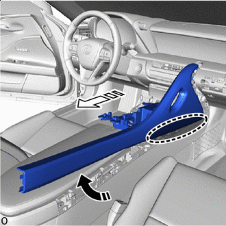
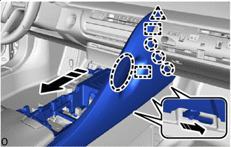
Place Hands Here Remove in this Direction (1) 
Remove in this Direction (2) Pull diagonally to the upper rear of the vehicle as indicated by the arrows shown in the illustration to remove the console upper panel sub-assembly.
Note
A portion of the claw is inserted into mating hole. Therefore, hold the area shown in the illustration and remove it while lifting the claw towards the outside of the vehicle.
-
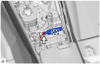
Connect the connector.
-
Detach the clamp and remove the No. 1 indoor electrical key antenna assembly.
Note
Do not reuse dropped or damaged parts.
-