FRAME WIRE REMOVAL
CAUTION / NOTICE / HINT
The necessary procedures (adjustment, calibration, initialization, or registration) that must be performed after parts are removed and installed, or replaced during HV floor under wire removal/installation are shown below.
| Replaced Part or Performed Procedure | Necessary Procedures | Effect/Inoperative Function when Necessary Procedure not Performed | Link |
|---|---|---|---|
| Disconnect cable from negative auxiliary battery terminal | Memorize steering angle neutral point | LKA/LDA system | |
| Pre-collision system | |||
| Parking assist monitor system | |||
| Steering sensor zero point calibration | Variable gear ratio steering system | ||
| ECM | Vehicle Identification Number (VIN) registration | DTC P063051 is output | w/ Canister Pump Module: w/o Canister Pump Module: |
|
Inspection after repair |
|
w/ Canister Pump Module: w/o Canister Pump Module: |
| Engine assembly | Inspection after repair | ||
| Drive learning*1 |
|
||
| Parts between the steering wheel and tires have been removed/installed, replaced or adjusted | Perform Actuator Angle Neutral Point Calibration and Initialization |
|
|
| Suspension, tires, etc*2 | Television camera assembly optical axis (Back camera position setting) | Parking assist monitor system | |
| Front seat assembly RH (Only for removal and installation) | Initialize position control ECU | Front Power Seat Control System |
*2: The vehicle height changes due to suspension or tire replacement.
CAUTION:
-
Orange wire harnesses and connectors indicate high-voltage circuits. To prevent electric shock, always follow the procedure described in the repair manual.
-
To prevent electric shock, wear insulated gloves when working on wire harnesses and components of the high voltage system.
PROCEDURE
-
PRECAUTION
Note
After turning the power switch off, waiting time may be required before disconnecting the cable from the negative (-) auxiliary battery terminal. Therefore, make sure to read the disconnecting the cable from the negative (-) auxiliary battery terminal notices before proceeding with work.
-
REMOVE NO. 2 DECK BOARD
-
DISCONNECT CABLE FROM NEGATIVE AUXILIARY BATTERY TERMINAL
Note
When disconnecting the cable, some systems need to be initialized after the cable is reconnected.
-
REMOVE SERVICE PLUG GRIP
-
REMOVE CONNECTOR COVER ASSEMBLY
-
CHECK TERMINAL VOLTAGE
-
TEMPORARILY INSTALL CONNECTOR COVER ASSEMBLY
-
REMOVE ENGINE ASSEMBLY WITH TRANSMISSION
-
REMOVE FUEL TANK ASSEMBLY
-
w/ Canister Pump Module:
-
w/o Canister Pump Module:
-
-
REMOVE FRONT SEAT ASSEMBLY RH
-
REMOVE REAR SEAT ASSEMBLY
-
REMOVE REAR SEAT SPEAKER
-
REMOVE FRONT DOOR SCUFF PLATE RH
-
REMOVE OUTER LAP BELT ANCHOR COVER
-
DISCONNECT FRONT OUTER SEAT BELT ASSEMBLY RH
-
REMOVE QUARTER INSIDE TRIM BOARD RH
-
REMOVE REAR INNER SEAT BELT ASSEMBLY RH
Tech Tips
Use the same procedure described for the rear No. 1 seat inner belt assembly LH.
-
REMOVE QUARTER TRIM PANEL ASSEMBLY RH
-
REMOVE NO. 1 HYBRID BATTERY INTAKE DUCT
-
REMOVE NO. 2 HYBRID BATTERY INTAKE DUCT
-
REMOVE NO. 10 HV BATTERY SHIELD PANEL
-
REMOVE FRONT NO. 6 FLOOR HEAT INSULATOR
-
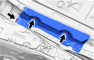
Remove the 3 nuts and front No. 6 floor heat insulator.
-
-
REMOVE FRONT NO. 5 FLOOR HEAT INSULATOR
-
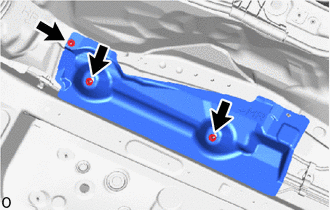
Remove the 3 nuts and front No. 5 floor heat insulator.
-
-
REMOVE FRONT NO. 2 FLOOR HEAT INSULATOR SUB-ASSEMBLY
-
Remove the 2 bolts and front No. 2 floor heat insulator sub-assembly.
-
-
REMOVE FRONT NO. 1 FLOOR HEAT INSULATOR SUB-ASSEMBLY
-
Remove the 2 bolts and front No. 1 floor heat insulator sub-assembly.
-
-
REMOVE HV FLOOR UNDER WIRE
CAUTION:
Wear insulated gloves.
-
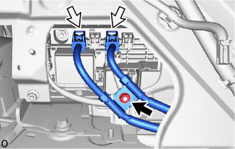
Remove the nut and disconnect the 2 connectors.
-
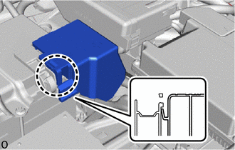
Detach the claw and Remove the battery terminal connector cover.
-
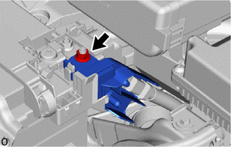
Remove the nut and disconnect the HV floor under wire.
-
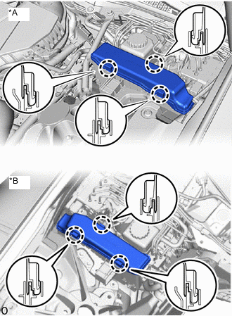
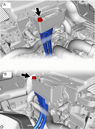
*A for LHD *B for RHD Detach the 3 claws and Remove the relay block cover.
-
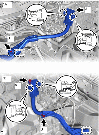
*A for LHD *B for RHD Remove the bolt A.
-
Detach the 2 claws and disconnect the HV floor under wire from the engine room relay block.
-
Remove the bolt B.
-
Detach the clamp.
-
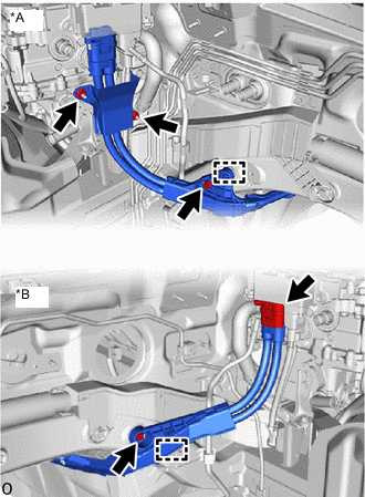
*A for LHD *B for RHD for LHD:
Remove the 2 nuts and wiring harness clamp bracket.
-
Remove the bolt.
-
Detach the clamp.
-
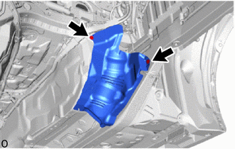
Remove the connector cover assembly.
-
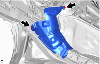
*A for LHD *B for RHD Remove the bolt.
-
Disconnect the HV floor under wire.
Note
-
Do not allow any foreign matter or water to enter the inverter with converter assembly.
-
Do not touch the connector waterproofing rubber or terminals.
-
Do not damage the connectors, connector housings or inverter with converter assembly during disconnection.
-
Insulate the removed connectors with insulating tape.
-
Cover the hole where the cable was connected with tape (non-residue type) or equivalent to prevent entry of foreign matter.
-
-
Temporarily install the connector cover assembly.
-
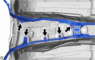
Remove the 5 nuts.
-
Detach the clamp.
-
Remove the 2 nuts.
-
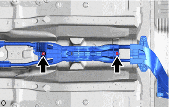
*1 Stud Clamp Remove the 2 bolts.
-
Remove the 2 nuts.
-
Detach the clamp.
-
Detach the grommet and pull out the hybrid under floor wire to the outside of the vehicle.
-
Remove the stud clamp.
Tech Tips
When removing the stud clamp, break the claw on the stud clamp. The stud clamp cannot be reused.
-
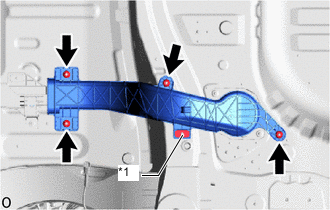
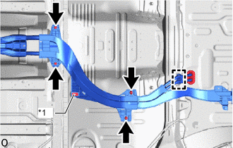
*1 Stud Clamp Remove the 4 nuts.
-
Remove the stud clamp and wiring harness protector.
Tech Tips
When removing the stud clamp, break the claw on the stud clamp. The stud clamp cannot be reused.
-
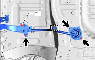
*1 Stud Clamp Detach the clamp.
-
Remove the 3 nuts and pull out the hybrid under floor wire to the outside of the vehicle.
-
Remove the stud clamp.
Tech Tips
When removing the stud clamp, break the claw on the stud clamp. The stud clamp cannot be reused.
-