HYBRID CONTROL SYSTEM, Diagnostic DTC:P253012
| DTC Code | DTC Name |
|---|---|
| P253012 | IG2 Signal Circuit Short to Auxiliary Battery |
DESCRIPTION
The hybrid vehicle control ECU assembly compares the IG2 signal to the IG control status signal sent from the certification ECU (smart key ECU assembly) to detect a stuck on malfunction of the IG2 signal.
Tech Tips
If DTC P253012 is stored, the power switch will turn off (READY off).
| DTC No. | Detection Item | DTC Detection Condition | Trouble Area | MIL | Warning Indicate |
|---|---|---|---|---|---|
| P253012 | IG2 Signal Circuit Short to Auxiliary Battery | The IG2 signal of the hybrid vehicle control ECU assembly and the IG control status signal sent from the certification ECU (smart key ECU assembly) do not match. (1 trip detection logic) |
|
Does not come on | Master Warning Light: Comes on |
CONFIRMATION DRIVING PATTERN
Tech Tips
After repairs have been completed, clear the DTCs and then check that the vehicle has returned to normal by performing the following All Readiness check procedure.
-
Connect the GTS to the DLC3.
-
Turn the power switch on (IG) and turn the GTS on.
-
Clear the DTCs (even if no DTCs are stored, perform the clear DTC procedure).
-
Turn the power switch off and wait for 2 minutes or more.
-
Turn the power switch on (IG) and wait for 15 seconds or more.
-
Turn the power switch off and wait for 2 minutes or more.
-
Turn the power switch on (IG) and turn the GTS on.
-
Enter the following menus: Powertrain / Hybrid Control / Utility / All Readiness.
-
Check the DTC judgment result.
Tech Tips
-
If the judgment result shows NORMAL, the system is normal.
-
If the judgment result shows ABNORMAL, the system has a malfunction.
-
If the judgment result shows INCOMPLETE or N/A, perform driving pattern again.
-
WIRING DIAGRAM
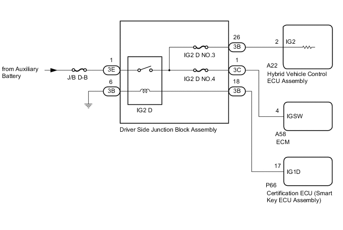
CAUTION / NOTICE / HINT
Note
Before replacing the certification ECU (smart key ECU assembly), refer to Registration.
PROCEDURE
-
CHECK AUXILIARY BATTERY VOLTAGE
-
Turn the power switch off and turn on the high beam headlights for 30 seconds. This will remove the surface charge from the auxiliary battery.
-
Measure the auxiliary battery voltage according to the value(s) in the table below.
Standard Voltage Tester Connection Condition Specified Condition Positive (+) auxiliary battery terminal - Negative (-) auxiliary battery terminal 20°C (68°F), Power switch off 11.0 V or higher Result Proceed to OK NG
NG 
CHARGE OR REPLACE AUXILIARY BATTERY Click here
OK 
-
-
CLEAR DTC
-
Connect the GTS to the DLC3.
-
Turn the power switch on (IG).
-
Enter the following menus: Powertrain / Hybrid Control / Trouble Codes.
-
Clear the DTCs.
Powertrain > Hybrid Control > Clear DTCs -
Turn the power switch off.
Result Proceed to NEXT
NEXT
-
-
CHECK DTC OUTPUT (HYBRID CONTROL)
-
Turn the power switch on (IG) and wait for 15 seconds or more.
-
Turn the power switch off and wait for 2 minutes or more.
-
Connect the GTS to the DLC3.
-
Turn the power switch on (IG).
-
Enter the following menus: Powertrain / Hybrid Control / Trouble Codes.
-
Check for DTCs.
Powertrain > Hybrid Control > Trouble CodesResult Result Proceed to P253012 is output. A P253012 is not output. B -
Turn the power switch off.
B 
CHECK FOR INTERMITTENT PROBLEMS Click here
A
-
-
CHECK DTC OUTPUT (HYBRID CONTROL)
-
Connect the GTS to the DLC3.
-
Turn the power switch on (IG).
-
Enter the following menus: Powertrain / Hybrid Control / Trouble Codes.
-
Check for DTCs.
Powertrain > Hybrid Control > Trouble CodesResult Result Proceed to U011087, U012987, U014087, U015187, U016487 or U117087 is not output. A U011087, U012987, U014087, U015187, U016487 or U117087 is also output. B -
Turn the power switch off.
B
REPLACE CERTIFICATION ECU (SMART KEY ECU ASSEMBLY)
A
-
-
CHECK HYBRID VEHICLE CONTROL ECU ASSEMBLY
-
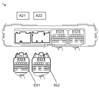
*a Rear view of wire harness connector
(to Hybrid Vehicle Control ECU Assembly)
Disconnect the A21 and A22 hybrid vehicle control ECU assembly connectors.
-
Measure the voltage according to the value(s) in the table below.
Standard Voltage Tester Connection Condition Specified Condition A22-2 (IG2) - A21-2 (E01) Power switch off 9 V or higher -
Reconnect the A21 and A22 hybrid vehicle control ECU assembly connectors.
Result Proceed to OK NG
NG
REPLACE HYBRID VEHICLE CONTROL ECU ASSEMBLY Click here
OK
-
-
CHECK ECM
-
*a Rear view of wire harness connector
(to Hybrid Vehicle Control ECU Assembly)
Disconnect the A21 and A22 hybrid vehicle control ECU assembly connectors.
-
Disconnect the A58 ECM connector.
-
Measure the voltage according to the value(s) in the table below.
Standard Voltage Tester Connection Condition Specified Condition A22-2 (IG2) - A21-2 (E01) Power switch off 9 V or higher -
Reconnect the A58 ECM connector.
-
Reconnect the A21 and A22 hybrid vehicle control ECU assembly connectors.
Result Proceed to OK NG
NG
REPLACE ECM Click here
OK
-
-
INSPECT DRIVER SIDE JUNCTION BLOCK ASSEMBLY (IG2 D RELAY)
Result Proceed to OK NG
-
Remove the driver side junction block assembly.
-
Reconnect the driver side junction block assembly connectors.
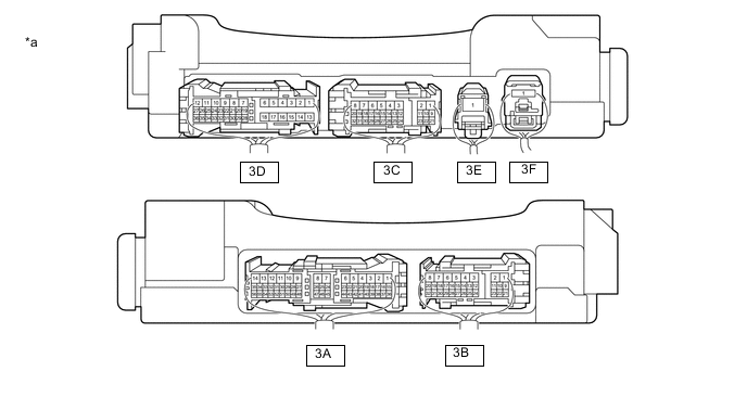
*a Component with harness connected
(Driver Side Junction Block Assembly)
- - -
Measure the voltage according to the value(s) in the table below.
Standard Voltage Tester Connection Switch Condition Specified Condition 3B-32 - Body ground Power switch on (IG) 11 to 14 V 3A-17 - Body ground Power switch on (IG) 9 to 14 V 3B-28 - Body ground Power switch on (IG) 11 to 14 V 3C-27 - Body ground Power switch on (IG) 9 to 14 V 3C-28 - Body ground Power switch on (IG) 9 to 14 V 3D-9 - Body ground Power switch on (IG) 11 to 14 V 3D-10 - Body ground Power switch on (IG) 9 to 14 V 3A-53 - Body ground Power switch on (IG) 11 to 14 V Result Proceed to OK NG
NG
REPLACE DRIVER SIDE JUNCTION BLOCK ASSEMBLY (IG2 D RELAY)
OK
-
-
CHECK HARNESS AND CONNECTOR (HYBRID VEHICLE CONTROL ECU ASSEMBLY - DRIVER SIDE JUNCTION BLOCK ASSEMBLY)
-
Disconnect the A22 hybrid vehicle control ECU assembly connector.
-
Remove the driver side junction block assembly.
-
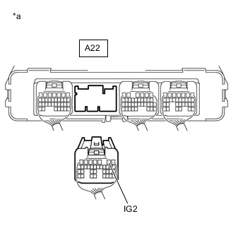
*a Rear view of wire harness connector
(to Hybrid Vehicle Control ECU Assembly)
Measure the voltage according to the value(s) in the table below.
Standard Voltage Tester Connection Condition Specified Condition A22-2 (IG2) - Body ground Power switch off 1 V or less -
Install the driver side junction block assembly.
-
Reconnect the A22 hybrid vehicle control ECU assembly connector.
Result Proceed to OK NG
OK
Check for intermittent problems. Click here Check the connection and terminal contact pressure of the connectors and wire harnesses between the hybrid vehicle control ECU assembly and the driver side junction block assembly. When the power switch is on (READY), jiggle the connectors and wire harnesses between the hybrid vehicle control ECU assembly and the driver side junction block assembly.
NG
REPAIR OR REPLACE HARNESS OR CONNECTOR
-
-
CHARGE OR REPLACE AUXILIARY BATTERY
-
Charge or replace the auxiliary battery.
Result Proceed to NEXT
NEXT
GO TO STEP 2 Click here
-