HYBRID CONTROL SYSTEM, Diagnostic DTC:P1C8149, P1C8249
| DTC Code | DTC Name |
|---|---|
| P1C8149 | High Voltage Power Resource Circuit Consumption Circuit Short |
| P1C8249 | High Voltage Power Resource Circuit Over Loading |
DTC SUMMARY
-
MALFUNCTION DESCRIPTION
The hybrid vehicle control ECU assembly monitors the high-voltage wiring between the HV battery and inverter with converter assembly and detects a short circuit malfunction or high-voltage system operation malfunction.
The cause of this malfunction may be one of the following:
-
Battery current sensor (IB) malfunction
-
Motor generator control ECU (MG ECU) malfunction
-
Communication (wire harness) malfunction
Battery current sensor (IB) circuit malfunction
-
HV battery malfunction
-
HV battery junction block assembly malfunction
-
Inverter with converter assembly malfunction
-
Air conditioner system malfunction
-
High-voltage wire harness malfunction
-
High-voltage connector or connection malfunction
High voltage system malfunction
-
Hybrid vehicle control ECU assembly malfunction
-
Low voltage wire harness malfunction
-
Low voltage connector malfunction
Low-voltage circuit (12 V) malfunction
-
-
INSPECTION DESCRIPTION
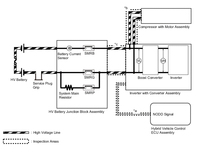
System Diagram Location Inspection Content Reason Inspection Step *a Check wire harness connector connection condition between hybrid vehicle control ECU assembly and inverter with converter assembly Check that DC/DC can be cut off normally during precharge.
-
Check for open or short circuit in the NODD line
-
Check that NODD terminal voltage is sufficiently low during DC/DC operation command.
2 to 5 *b Check high-voltage wiring connection condition of the air conditioner compressor with motor assembly Check for short circuit 6, 8 *c Check the high voltage cables between the HV battery junction block assembly and inverter with converter assembly. Check for short circuit 7, 9 -
DESCRIPTION
Refer to the description for DTC P0AE411.
| DTC No. | Detection Item | DTC Detection Condition | Trouble Area | MIL | Warning Indicate |
|---|---|---|---|---|---|
| P1C8149 | High Voltage Power Resource Circuit Consumption Circuit Short | High-voltage circuit malfunctions between the HV battery and inverter with converter assembly. Excessive overcurrent equal to a short occurs during precharge (time from when SMRP turns on until SMRG turns on). (1 trip detection logic) |
|
Does not come on | Master Warning Light: Comes on |
| P1C8249 | High Voltage Power Resource Circuit Over Loading | High-voltage circuit malfunctions between the HV battery and inverter with converter assembly. Small battery overcurrent occurs during precharge (time from when SMRP turns on until SMRG turns on) and current continues to flow after precharge. (1 trip detection logic) |
|
Does not come on | Master Warning Light: Comes on |
| DTC No. | Data List |
|---|---|
| P1C8149 |
|
| P1C8249 |
CONFIRMATION DRIVING PATTERN
Tech Tips
After repairs have been completed, clear the DTCs and then check that the vehicle has returned to normal by performing the following All Readiness check procedure.
-
Connect the GTS to the DLC3.
-
Turn the power switch on (IG) and turn the GTS on.
-
Clear the DTCs (even if no DTCs are stored, perform the clear DTC procedure).
-
Turn the power switch off and wait for 2 minutes or more.
-
Turn the power switch on (READY) and wait for 30 seconds or more.
-
Turn the power switch off and wait for 30 seconds or more.
-
Turn the power switch on (IG) and turn the GTS on.
-
Enter the following menus: Powertrain / Hybrid Control / Utility / All Readiness.
-
Check the DTC judgment result.
Tech Tips
-
If the judgment result shows NORMAL, the system is normal.
-
If the judgment result shows ABNORMAL, the system has a malfunction.
-
If the judgment result shows INCOMPLETE or N/A, perform driving pattern again.
-
WIRING DIAGRAM
Refer to the wiring diagram for DTC P0AA649.
Refer to the wiring diagram for DTC P1CCC96.
CAUTION / NOTICE / HINT
CAUTION:
-
If this DTC is output, do not turn the power switch on (READY) until the repair has been completed. This DTC means an excessive amperage flow through the system main resistor. The system main resistor may overheat and be damaged if the power switch is turned on (READY) repeatedly before repair.
-
Before the following operations are conducted, take precautions to prevent electric shock by turning the power switch off, wearing insulated gloves, and removing the service plug grip from HV battery.
-
Inspecting the high-voltage system
-
Disconnecting the low voltage connector of the inverter with converter assembly
-
Disconnecting the low voltage connector of the HV battery
-
To prevent electric shock, make sure to remove the service plug grip to cut off the high voltage circuit before servicing the vehicle.
-
After removing the service plug grip from the HV battery, put it in your pocket to prevent other technicians from accidentally reconnecting it while you are working on the high-voltage system.
-
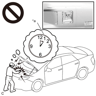
*a Without waiting for 10 minutes After removing the service plug grip, wait for at least 10 minutes before touching any of the high-voltage connectors or terminals. After waiting for 10 minutes, check the voltage at the terminals in the inspection point in the inverter with converter assembly. The voltage should be 0 V before beginning work.
Tech Tips
Waiting for at least 10 minutes is required to discharge the high-voltage capacitor inside the inverter with converter assembly.
Note
After turning the power switch off, waiting time may be required before disconnecting the cable from the negative (-) auxiliary battery terminal. Therefore, make sure to read the disconnecting the cable from the negative (-) auxiliary battery terminal notices before proceeding with work.
PROCEDURE
-
CHECK DTC OUTPUT (HYBRID CONTROL, MOTOR GENERATOR, HV BATTERY)
-
Connect the GTS to the DLC3.
-
Turn the power switch on (IG).
-
Enter the following menus: Powertrain / Hybrid Control, Motor Generator, HV Battery / Trouble Codes.
-
Check for DTCs.
Powertrain > Hybrid Control > Trouble Codes
Powertrain > Motor Generator > Trouble Codes
Powertrain > HV Battery > Trouble CodesResult Result Proceed to P1C8149 or P1C8249 only is output, or DTCs except the ones in the tables below are also output. A DTCs of hybrid control system in the tables below are output. B DTCs of motor generator control system in the tables below are output. C DTCs of hybrid battery system in the tables below are output. D Malfunction Content System Relevant DTC Microcomputer malfunction Hybrid control system P060647 Hybrid/EV Powertrain Control Module Processor Watchdog / Safety MCU Failure P060B49 Hybrid/EV Powertrain Control Module A/D Processing Internal Electronic Failure P060687 Hybrid/EV Powertrain Control Module Processor to Monitoring Processor Missing Message P060A47 Hybrid/EV Powertrain Control Module Monitoring Processor Watchdog / Safety MCU Failure P060A87 Hybrid/EV Powertrain Control Module Processor from Monitoring Processor Missing Message Hybrid battery system P060B49 Hybrid/EV Battery Energy Control Module A/D Processing Internal Electronic Failure P060687 Hybrid/EV Battery Energy Control Module Processor to Monitoring Processor Missing Message P060A47 Hybrid/EV Battery Energy Control Module Monitoring Processor Watchdog / Safety MCU Failure P060A87 Hybrid/EV Battery Energy Control Module Processor from Monitoring Processor Missing Message P060B16 Hybrid/EV Battery Energy Control Module A/D Processing Circuit Voltage Below Threshold P0E2D00 Hybrid/EV Battery Energy Control Module Hybrid/EV Battery Monitor Performance Communication system malfunction Hybrid control system U011187 Lost Communication with Hybrid/EV Battery Energy Control Module "A" Missing Message Sensor and actuator circuit malfunction Hybrid control system P0B231C Hybrid/EV Battery "A" Voltage Sensor Voltage Out of Range P0ABF00 Hybrid/EV Battery Current Sensor "A" Circuit Range/Performance Motor generator control system P0A1114 DC/DC Converter Enable Circuit Short to Ground or Open P0A1112 DC/DC Converter Enable Circuit Short to Battery P1CCC96 DC/DC Converter Enable Component Internal Failure Hybrid battery system P0ABF11 Hybrid/EV Battery Current Sensor "A" Circuit Short to Ground P0B0E11 Hybrid/EV Battery Current Sensor "B" Circuit Short to Ground P0B0E15 Hybrid/EV Battery Current Sensor "B" Circuit Short to Auxiliary Battery or Open P0ABF15 Hybrid/EV Battery Current Sensor "A" Circuit Short to Auxiliary Battery or Open P301A1C Hybrid Battery Stack 1 Cell Voltage Detection Voltage Out of Range P1A001C Hybrid Battery Stack 2 Cell Voltage Detection Voltage Out of Range P1AFD1C Flying Capacitor/Internal Control Module Hybrid/EV Battery Monitor Voltage Out of Range P0ABF28 Hybrid/EV Battery Current Sensor "A" Signal Bias Level Out of Range / Zero Adjustment Failure P0ABF2A Hybrid/EV Battery Current Sensor "A" Signal Stuck In Range P1CBB12 Hybrid/EV Battery Current Sensor Power Supply Circuit Short to Auxiliary Battery P1CBB14 Hybrid/EV Battery Current Sensor Power Supply Circuit Short to Ground or Open P0B1362 Hybrid/EV Battery Current Sensor "A"/"B" Signal Compare Failure System malfunction Hybrid control system P0A1F94 Hybrid/EV Battery Energy Control Module Unexpected Operation Motor generator control system P0D3319 DC/DC Converter Circuit Current Above Threshold Tech Tips
-
P1C8149 or P1C8249 may be output as a result of the malfunction indicated by the DTCs above.
-
The chart above is listed in inspection order of priority.
-
Check DTCs that are output at the same time by following the listed order. (The main cause of the malfunction can be determined without performing unnecessary inspections.)
-
-
Turn the power switch off.
B 
GO TO DTC CHART (HYBRID CONTROL SYSTEM) Click here
C
GO TO DTC CHART (MOTOR GENERATOR CONTROL SYSTEM) Click here
D
GO TO DTC CHART (HYBRID BATTERY SYSTEM) Click here
A 
-
-
CHECK CONNECTOR CONNECTION CONDITION (HYBRID VEHICLE CONTROL ECU ASSEMBLY CONNECTOR)
Result Proceed to OK NG
-
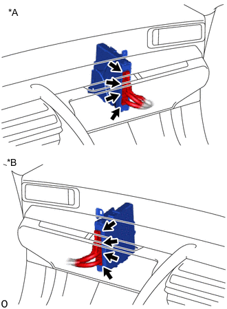
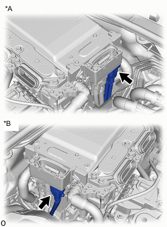
*A for LHD *B for RHD Check the connector connections and contact pressure of the relevant terminals for the hybrid vehicle control ECU assembly connectors.
OK The connectors are connected securely and there are no contact pressure problems. Result Proceed to OK NG
NG
CONNECT SECURELY
OK
-
-
CHECK CONNECTOR CONNECTION CONDITION (INVERTER WITH CONVERTER ASSEMBLY CONNECTOR)
Result Result Proceed to OK A NG (The connector is not connected securely.) B NG (The terminals are not making secure contact or are deformed, or water or foreign matter exists in the connector.) C CAUTION:
Be sure to wear insulated gloves.
-
Check that the service plug grip is not installed.
Note
After removing the service plug grip, do not turn the power switch on (READY), unless instructed by the repair manual because this may cause a malfunction.
-
Check the connection condition of the low voltage connectors of the inverter with converter assembly and the contact pressure of each terminal. Check the terminals for deformation, and the connector for water and foreign matter.
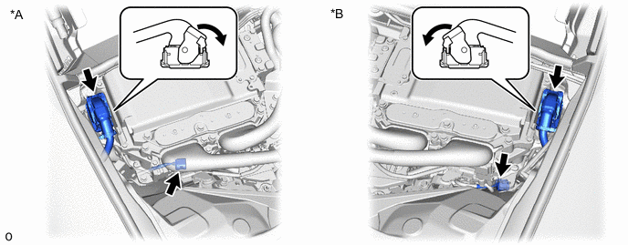
*A for LHD *B for RHD Note
Before disconnecting the connector, confirm that it is properly connected by checking that the claws of the lock levers are engaged and that the connector cannot be pulled off.
OK - The connector is connected securely. - The terminals are not deformed and are connected securely. - No water or foreign matter in the connector. Result Result Proceed to OK A NG (The connector is not connected securely.) B NG (The terminals are not making secure contact or are deformed, or water or foreign matter exists in the connector.) C Tech Tips
When connecting the connector, connect it with the lock levers raised. Rotate each lock lever downward and make sure that the connector is securely connected. When a lock lever is fully lowered, a click will be heard as its claw engages. After the click is heard, pull up on the connector to confirm that it is securely connected.
B
CONNECT SECURELY
C
REPAIR OR REPLACE HARNESS OR CONNECTOR
A
-
-
CHECK HARNESS AND CONNECTOR (INVERTER WITH CONVERTER ASSEMBLY - HYBRID VEHICLE CONTROL ECU ASSEMBLY)
CAUTION:
Be sure to wear insulated gloves.
-
Check that the service plug grip is not installed.
Note
After removing the service plug grip, do not turn the power switch on (READY), unless instructed by the repair manual because this may cause a malfunction.
-
Disconnect the A25 inverter with converter assembly connector.
-
Disconnect the A22 hybrid vehicle control ECU assembly connector.
-
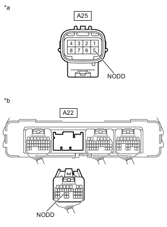
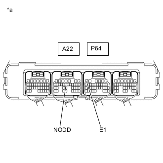
*a Front view of wire harness connector
(to Inverter with Converter Assembly)
*b Rear view of wire harness connector
(to Hybrid Vehicle Control ECU Assembly)
Measure the resistance according to the value(s) in the table below.
Standard Resistance (Check for Open) Tester Connection Condition Specified Condition A25-5 (NODD) - A22-14 (NODD) Power switch off Below 1 Ω Standard Resistance (Check for Short) Tester Connection Condition Specified Condition A25-5 (NODD) or A22-14 (NODD) - Body ground and other terminals Power switch off 10 kΩ or higher -
Reconnect the A22 hybrid vehicle control ECU assembly connector.
-
Reconnect the A25 inverter with converter assembly connector.
Result Proceed to OK NG
NG
REPAIR OR REPLACE HARNESS OR CONNECTOR
OK
-
-
CHECK HYBRID VEHICLE CONTROL ECU ASSEMBLY
CAUTION:
Be sure to wear insulated gloves.
-
Connect the cable to the negative (-) auxiliary battery terminal.
-
Turn the power switch on (IG).
-
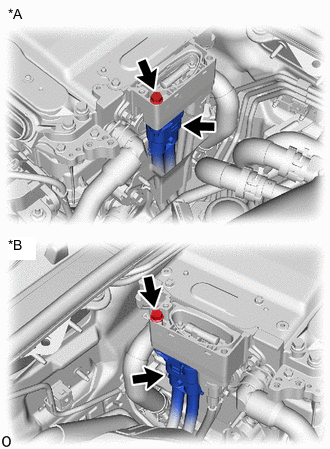
*a Component with harness connected
(Hybrid Vehicle Control ECU Assembly)
Measure the voltage according to the value(s) in the table below.
Standard Voltage Tester Connection Condition Specified Condition A22-14 (NODD) - P64-6 (E1) Power switch on (IG) Below 1.5 V -
Turn the power switch off.
-
Disconnect the cable from the negative (-) auxiliary battery terminal.
Result Proceed to OK NG
NG
REPLACE HYBRID VEHICLE CONTROL ECU ASSEMBLY Click here
OK
-
-
CHECK COMPRESSOR WITH MOTOR ASSEMBLY
CAUTION:
Be sure to wear insulated gloves.
-
Check that the service plug grip is not installed.
Note
After removing the service plug grip, do not turn the power switch on (READY), unless instructed by the repair manual because this may cause a malfunction.
-
*A for LHD *B for RHD Disconnect the HV air conditioning wire connector from the inverter with converter assembly.
-
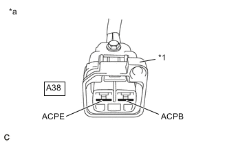
*1 Shield Ground *a HV Air Conditioning Wire
(Inverter with Converter Assembly Side)
Measure the resistance according to the value(s) in the table below.
Standard Resistance Tester Connection
(Tester Probe Polarity)
Condition Specified Condition A38-1 (ACPE) (Negative (-) probe) - A38-2 (ACPB) (Positive (+) probe) Power switch off 100 kΩ or higher Note
-
Do not use a megohmmeter.
-
Read the resistance after the value has stabilized.
-
Be sure to inspect with connecting the tester probes to the tips of the terminal.
-
-
Reconnect the HV air conditioning wire connector.
Result Proceed to OK NG
NG 
CHECK HV AIR CONDITIONING WIRE Click here
OK
-
-
CHECK HV FLOOR UNDER WIRE
CAUTION:
Be sure to wear insulated gloves.
-
Check that the service plug grip is not installed.
Note
After removing the service plug grip, do not turn the power switch on (READY), unless instructed by the repair manual because this may cause a malfunction.
-
*A for LHD *B for RHD Disconnect the HV floor under wire connector from the inverter with converter assembly.
-
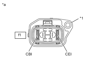
*1 Shield Ground *a HV Floor Under Wire
(Inverter with Converter Assembly Side)
Measure the resistance according to the value(s) in the table below.
Standard Resistance Tester Connection Condition Specified Condition f1-1 (CBI) - f1-2 (CEI) Power switch off 10 kΩ or higher Note
Be sure not to damage or deform the terminal being inspected.
-
Reconnect the HV floor under wire connector.
Result Proceed to OK NG
OK
REPLACE INVERTER WITH CONVERTER ASSEMBLY Click here
NG
CHECK HV FLOOR UNDER WIRE Click here
-
-
CHECK HV AIR CONDITIONING WIRE
CAUTION:
Be sure to wear insulated gloves.
-
Check that the service plug grip is not installed.
Note
After removing the service plug grip, do not turn the power switch on (READY), unless instructed by the repair manual because this may cause a malfunction.
-
*A for LHD *B for RHD Disconnect the HV air conditioning wire connector from the inverter with converter assembly.
-
*1 Green Lock Disconnect the HV air conditioning wire from the compressor with motor assembly.
-
*1 Shield Ground *a HV Air Conditioning Wire
(Inverter with Converter Assembly Side)
Measure the resistance according to the value(s) in the table below.
Standard Resistance Tester Connection Condition Specified Condition A38-1 (ACPE) - A38-2 (ACPB) Power switch off 10 kΩ or higher Note
Be sure to inspect with connecting the tester probes to the tips of the terminal.
-
Reconnect the HV air conditioning wire connector to the inverter with converter assembly.
-
Reconnect the HV air conditioning wire to the compressor with motor assembly.
Result Proceed to OK NG
OK
REPLACE COMPRESSOR WITH MOTOR ASSEMBLY Click here
NG
REPLACE HV AIR CONDITIONING WIRE
-
-
CHECK HV FLOOR UNDER WIRE
CAUTION:
Be sure to wear insulated gloves.
-
Check that the service plug grip is not installed.
Note
After removing the service plug grip, do not turn the power switch on (READY), unless instructed by the repair manual because this may cause a malfunction.
-
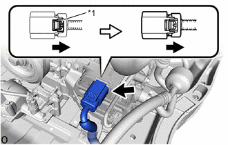
Remove the No. 10 HV battery shield panel.
-
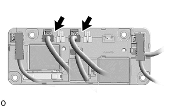
Disconnect the HV floor under wire connectors from the HV battery junction block assembly.
-
*A for LHD *B for RHD Disconnect the HV floor under wire connector from the inverter with converter assembly.
-
*1 Shield Ground *a HV Floor Under Wire
(Inverter with Converter Assembly Side)
Measure the resistance according to the value(s) in the table below.
Standard Resistance Tester Connection Condition Specified Condition f1-1 (CBI) - f1-2 (CEI) Power switch off 10 kΩ or higher Note
Be sure not to damage or deform the terminal being inspected.
-
Reconnect the HV floor under wire connector to the inverter with converter assembly.
-
Reconnect the HV floor under wire connectors to the HV battery junction block assembly.
-
Install the No. 10 HV battery shield panel.
Result Proceed to OK NG
OK
REPLACE HV BATTERY JUNCTION BLOCK ASSEMBLY Click here
NG
REPLACE HV FLOOR UNDER WIRE Click here
-