HYBRID CONTROL SYSTEM, Diagnostic DTC:P0A3611, P0A3615
| DTC Code | DTC Name |
|---|---|
| P0A3611 | Generator Temperature Sensor Circuit Short to Ground |
| P0A3615 | Generator Temperature Sensor Circuit Short to Auxiliary Battery or Open |
DTC SUMMARY
-
MALFUNCTION DESCRIPTION
These DTCs are stored when the generator temperature sensor output is abnormal. The cause of this malfunction may be one of the following:
-
Hybrid vehicle control ECU assembly malfunction
Hybrid vehicle control ECU assembly internal malfunction
-
Internal generator temperature sensor malfunction
-
Open or short in generator temperature sensor
Generator temperature sensor malfunction
-
The connectors are not connected properly
-
Foreign matter or water on the connector terminals
-
Open or short in wire harness
Wire harness between the generator temperature sensor and hybrid vehicle control ECU assembly
Tech Tips
If any of these DTCs are stored, the generator temperature sensor is malfunctioning and the self-protection function may not operate. Therefore under certain high load driving condition, the temperature of the generator (MG1) becomes high. If the self-protection function does not operate, the generator (MG1) may malfunction and cause the vehicle to enter fail-safe mode.
-
DESCRIPTION
The resistance of the thermistor built into the generator temperature sensor changes in accordance with changes in generator (MG1) temperature. The lower the generator (MG1) temperature, the higher the thermistor resistance. Conversely, the higher the generator (MG1) temperature, the lower the resistance.
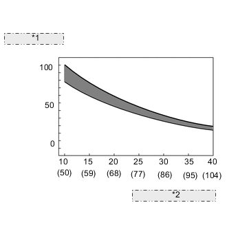
| *1 | Resistance (kΩ) |
| *2 | Temperature (°C (°F)) |
| DTC No. | Detection Item | DTC Detection Condition | Trouble Area | MIL | Warning Indicate |
|---|---|---|---|---|---|
| P0A3611 | Generator Temperature Sensor Circuit Short to Ground | Short to ground in the generator temperature sensor circuit (1 trip detection logic) |
|
Comes on | Master Warning Light: Comes on |
| P0A3615 | Generator Temperature Sensor Circuit Short to Auxiliary Battery or Open | Open or short to +B in the generator temperature sensor circuit (1 trip detection logic) |
|
Comes on | Master Warning Light: Comes on |
| DTC No. | Data List |
|---|---|
| P0A3611 | Generator Temperature |
| P0A3615 |
Tech Tips
After confirming that DTC P0A3611 or P0A3615 is output, use the GTS to check "Generator Temperature" in the Data List.
| Displayed Temperature | Malfunction |
|---|---|
| -40°C (-40°F) | Open circuit or short to +B |
| 215°C (419°F) | Short circuit or short to ground |
CONFIRMATION DRIVING PATTERN
Tech Tips
After repair has been completed, clear the DTC and then check that the vehicle has returned to normal by performing the following All Readiness check procedure.
Tech Tips
After repairs have been completed, clear the DTCs and then check that the vehicle has returned to normal by performing the following All Readiness check procedure.
-
Connect the GTS to the DLC3.
-
Turn the power switch on (IG) and turn the GTS on.
-
Clear the DTCs (even if no DTCs are stored, perform the clear DTC procedure).
-
Turn the power switch off and wait for 2 minutes or more.
-
Turn the power switch on (IG) and turn the GTS on.
-
With power switch on (IG) and wait for 5 seconds or more.
-
Enter the following menus: Powertrain / Hybrid Control / Utility / All Readiness.
-
Check the DTC judgment result.
Tech Tips
-
If the judgment result shows NORMAL, the system is normal.
-
If the judgment result shows ABNORMAL, the system has a malfunction.
-
If the judgment result shows INCOMPLETE or N/A, perform driving pattern again.
-
WIRING DIAGRAM
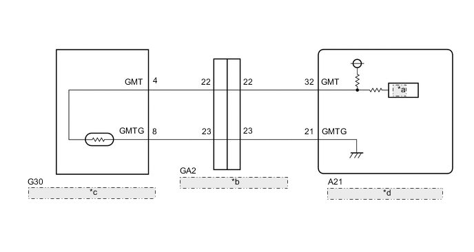
| *a | ADC |
| *b | No. 1 Engine Room Relay Block Connector |
| *c | Generator Temperature Sensor (Hybrid Vehicle Transmission Assembly) |
| *d | Hybrid Vehicle Control ECU Assembly |
PROCEDURE
-
CHECK CONNECTOR CONNECTION CONDITION (HYBRID VEHICLE CONTROL ECU ASSEMBLY CONNECTOR)
Result Result Proceed to OK A NG (The connector is not connected securely.) B NG (The terminals are not making secure contact or are deformed, or water or foreign matter exists in the connector.) C
-
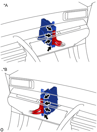
*A for LHD *B for RHD Check the connection condition of the hybrid vehicle control ECU assembly connectors and the contact pressure of each terminal. Check the terminals for deformation, and check the connector for water ingress and foreign matter.
OK - The connector is connected securely. - The terminals are not deformed and are connected securely. - No water or foreign matter in the connector. Result Result Proceed to OK A NG (The connector is not connected securely.) B NG (The terminals are not making secure contact or are deformed, or water or foreign matter exists in the connector.) C
B 
CONNECT SECURELY
C
REPAIR OR REPLACE HARNESS OR CONNECTOR
A 
-
-
READ VALUE USING GTS (GENERATOR TEMPERATURE)
-
Connect the GTS to the DLC3.
-
Turn the power switch on (IG).
-
Enter the following menus: Powertrain / Hybrid Control / Data List / Generator Temperature.
-
Read the Data List.
Powertrain > Hybrid Control > Data ListTester Display Generator Temperature Result Result Proceed to -40°C (-40°F) A 215°C (419°F) B Same as actual temperature C -
Turn the power switch off.
B 
CHECK GENERATOR TEMPERATURE SENSOR Click here
C
REPAIR OR REPLACE HARNESS OR CONNECTOR
A
-
-
CHECK HYBRID VEHICLE CONTROL ECU ASSEMBLY
-
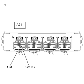
*a Component with harness connected
(to Hybrid Vehicle Control ECU Assembly)
Connect terminals 32 (GMT) and 21 (GMTG) of the A21 hybrid vehicle control ECU assembly.
-
Connect the GTS to the DLC3.
-
Turn the power switch on (IG).
-
Enter the following menus: Powertrain / Hybrid Control / Data List / Generator Temperature.
-
Read the Data List.
Powertrain > Hybrid Control > Data ListTester Display Generator Temperature OK Tester Display Condition Specified Condition Generator Temperature Terminals A21-32 (GMT) and A21-21 (GMTG) connected
Power switch on (IG)
215°C (419°F) -
Turn the power switch off.
Result Proceed to OK NG
NG
REPLACE HYBRID VEHICLE CONTROL ECU ASSEMBLY Click here
OK
-
-
CHECK CONNECTOR CONNECTION CONDITION (GENERATOR TEMPERATURE SENSOR CONNECTOR)
-
Check the connection condition of the generator temperature sensor connector and the contact pressure of each terminal. Check the terminals for deformation, and check the connector for water ingress and foreign matter.
OK - The connector is connected securely. - The terminals are not deformed and are connected securely. - No water or foreign matter in the connector. Result Result Proceed to OK A NG (The connector is not connected securely.) B NG (The terminals are not making secure contact or are deformed, or water or foreign matter exists in the connector.) C
B
CONNECT SECURELY
C
REPAIR OR REPLACE HARNESS OR CONNECTOR
A
-
-
INSPECT HYBRID VEHICLE TRANSMISSION ASSEMBLY (GENERATOR TEMPERATURE SENSOR)
-
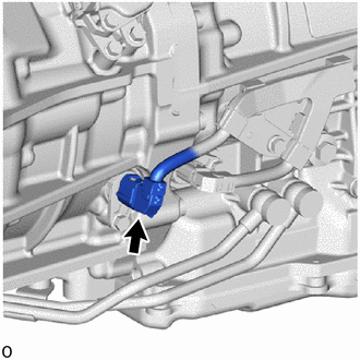
Disconnect the G30 generator temperature sensor connector.
-
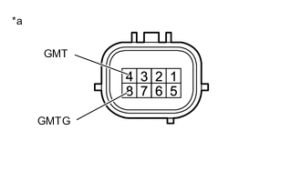
*a Component without harness connected
(Generator Temperature Sensor (Hybrid Vehicle Transmission Assembly))
Measure the resistance according to the value(s) in the table below.
Standard Resistance Tester Connection Condition Specified Condition 4 (GMT) - 8 (GMTG) Power switch OFF 0.3338 to 1487 kΩ -
Reconnect the G30 generator temperature sensor connector.
Result Proceed to OK NG
OK
REPAIR OR REPLACE HARNESS OR CONNECTOR
NG
REPLACE HYBRID VEHICLE TRANSMISSION ASSEMBLY Click here
-
-
CHECK GENERATOR TEMPERATURE SENSOR
-
Disconnect the GA2 No. 1 engine room relay block connector.
-
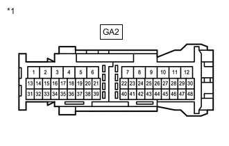
*1 No. 1 Engine Room Relay Block Connector Measure the resistance according to the value(s) in the table below.
Standard Resistance (Check for Open) Tester Connection Condition Specified Condition GA2-22 - GA2-23 Power switch off 0.3338 to 1487 kΩ Standard Resistance (Check for Short) Tester Connection Condition Specified Condition GA2-22 or GA2-23 - Body ground and other terminals Power switch off 10 kΩ or higher -
Reconnect the GA2 No. 1 engine room relay block connector.
Result Proceed to OK NG
NG
CHECK CONNECTOR CONNECTION CONDITION (GENERATOR TEMPERATURE SENSOR CONNECTOR) Click here
OK
-
-
CHECK HARNESS AND CONNECTOR (NO. 1 ENGINE ROOM RELAY BLOCK CONNECTOR - HYBRID VEHICLE CONTROL ECU ASSEMBLY)
-
Disconnect the GA2 No. 1 engine room relay block connector.
-
Disconnect the A21 hybrid vehicle control ECU assembly connector.
-
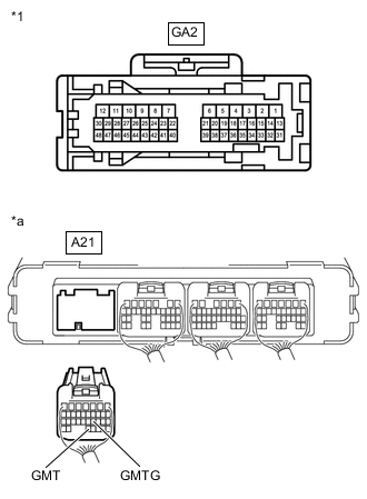
*1 No. 1 Engine Room Relay Block Connector *a Rear view of wire harness connector
(to Hybrid Vehicle Control ECU Assembly)
Measure the resistance according to the value(s) in the table below.
Standard Resistance (Check for Open) Tester Connection Condition Specified Condition GA2-22 - A21-32 (GMT) Power switch off Below 1 Ω GA2-23 - A21-21 (GMTG) Power switch off Below 1 Ω Standard Resistance (Check for Short) Tester Connection Condition Specified Condition GA2-22 or A21-32 (GMT) - Body ground and other terminals Power switch off 10 kΩ or higher GA2-23 or A21-21 (GMTG) - Body ground and other terminals Power switch off 10 kΩ or higher -
Reconnect the A21 hybrid vehicle control ECU assembly.
-
Reconnect the GA2 No. 1 engine room relay block connector.
Result Proceed to OK NG
OK
REPLACE HYBRID VEHICLE CONTROL ECU ASSEMBLY Click here
NG
REPAIR OR REPLACE HARNESS OR CONNECTOR
-
-
CHECK CONNECTOR CONNECTION CONDITION (GENERATOR TEMPERATURE SENSOR CONNECTOR)
-
Check the connection condition of the generator temperature sensor connector and the contact pressure of each terminal. Check the terminals for deformation, and check the connector for water ingress and foreign matter.
OK - The connector is connected securely. - The terminals are not deformed and are connected securely. - No water or foreign matter in the connector. Result Result Proceed to OK A NG (The connector is not connected securely.) B NG (The terminals are not making secure contact or are deformed, or water or foreign matter exists in the connector.) C
B
CONNECT SECURELY
C
REPAIR OR REPLACE HARNESS OR CONNECTOR
A
-
-
INSPECT HYBRID VEHICLE TRANSMISSION ASSEMBLY (GENERATOR TEMPERATURE SENSOR)
-
Disconnect the G30 generator temperature sensor connector.
-
*a Component without harness connected
(Generator Temperature Sensor (Hybrid Vehicle Transmission Assembly))
Measure the resistance according to the value(s) in the table below.
Standard Resistance Tester Connection Condition Specified Condition 4 (GMT) - 8 (GMTG) Power switch off 0.3338 to 1487 kΩ -
Reconnect the G30 generator temperature sensor connector.
Result Proceed to OK NG
OK
REPAIR OR REPLACE HARNESS OR CONNECTOR
NG
REPLACE HYBRID VEHICLE TRANSMISSION ASSEMBLY Click here
-