HYBRID CONTROL SYSTEM, Diagnostic DTC:P074513
| DTC Code | DTC Name |
|---|---|
| P074513 | Pressure Control Solenoid "A" Circuit Open |
DTC SUMMARY
-
MALFUNCTION DESCRIPTION
The system performs shifting from 1st to 4th gear with ON-OFF combinations of solenoid valves (SL1), (SL2), (SL3) and (SL4). The current from the hybrid vehicle control ECU assembly is detected as not flowing to SL1 according to operation commands. The cause of this malfunction may be one of the following:
-
Open or short between solenoid (SL1) valve and hybrid vehicle control ECU assembly
-
Solenoid (SL1) valve malfunction
-
DESCRIPTION
Based on the ON-OFF combinations of the solenoid (SL1, SL2, SL3 and SL4) valves, the hybrid vehicle control ECU assembly performs gear shifts from 1st gear to 4th gear.
If a circuit related to a solenoid valve is open or shorted, the hybrid vehicle control ECU assembly uses the fail-safe function to turn other solenoid valves ON or OFF.
Tech Tips
The following table shows normal operation of the solenoid (SL1) valve when the shift lever is in D.
| Gear | 1st | 2nd | 3rd | 4th |
|---|---|---|---|---|
| Solenoid (SL1) Valve | ON | ON | ON | OFF |
| DTC No. | Detection Item | DTC Detection Condition | Trouble Area | MIL | Warning Indicate |
|---|---|---|---|---|---|
| P074513 | Pressure Control Solenoid "A" Circuit Open | The current does not flow appropriately, even when operation commands are sent from the hybrid vehicle control ECU assembly to the solenoid (SL1) valve. (1-trip detection logic) |
|
Comes on | Master Warning Light: Comes on |
| DTC No. | Data List |
|---|---|
| P074513 | Solenoid (SL1)* |
-
*: SL1 solenoid forced operation request status. This item only changes when an Active Test is performed.
| DTC No. | Active Test |
|---|---|
| P074513 |
|
CONFIRMATION DRIVING PATTERN
Tech Tips
After repair has been completed, clear the DTC and then check that the vehicle has returned to normal by performing the following All Readiness check procedure.
-
Connect the GTS to the DLC3.
-
Turn the power switch on (IG) and turn the GTS on.
-
Clear the DTCs (even if no DTCs are stored, perform the clear DTC procedure).
-
Turn the power switch off and wait for 2 minutes or more.
-
Turn the power switch on (READY) and wait for 3 seconds or more.
-
Enter the following menus: Powertrain / Hybrid Control / Utility / All Readiness.
-
Check the DTC judgment result.
Tech Tips
-
If the judgment result shows NORMAL, the system is normal.
-
If the judgment result shows ABNORMAL, the system has a malfunction.
-
If the judgment result shows INCOMPLETE or N/A, perform the normal judgment procedure again.
-
WIRING DIAGRAM
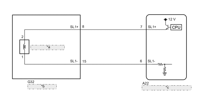
| *a | Solenoid (SL1) Valve |
| *b | Transmission Wire |
| *c | Hybrid Vehicle Control ECU Assembly |
PROCEDURE
-
CHECK HARNESS AND TRANSMISSION WIRE (TRANSMISSION WIRE (SOLENOID (SL1) VALVE) - HYBRID VEHICLE CONTROL ECU ASSEMBLY)
-
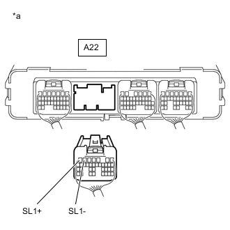
*a Rear view of wire harness connector
(to Hybrid Vehicle Control ECU Assembly)
Disconnect the A22 hybrid vehicle control ECU assembly connector.
-
Measure the resistance according to the value(s) in the table below.
Standard Resistance Tester Connection Condition Specified Condition A22-7 (SL1+) - A22-6 (SL1-) 20°C (68°F) 5.0 to 5.6 Ω A22-7 (SL1+) or A22-6 (SL1-) - Body ground Always 10 kΩ or higher -
Reconnect the A22 hybrid vehicle control ECU assembly connector.
Result Proceed to OK NG
OK 
REPLACE HYBRID VEHICLE CONTROL ECU ASSEMBLY Click here
NG 
-
-
CHECK HARNESS AND CONNECTOR (TRANSMISSION WIRE - HYBRID VEHICLE CONTROL ECU ASSEMBLY)
-
Disconnect the G32 transmission wire connector.
-
Disconnect the A22 hybrid vehicle control ECU assembly connector.
-
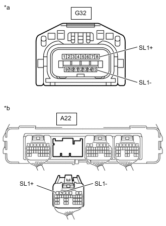
*a Front view of wire harness connector
(to Transmission Wire)
*b Rear view of wire harness connector
(to Hybrid Vehicle Control ECU Assembly)
Measure the resistance according to the value(s) in the table below.
Standard Resistance Tester Connection Condition Specified Condition G32-8 (SL1+) - A22-7 (SL1+) Always Below 1 Ω G32-15 (SL1-) - A22-6 (SL1-) Always Below 1 Ω G32-8 (SL1+) or A22-7 (SL1+) - Body ground Always 10 kΩ or higher G32-15 (SL1-) or A22-6 (SL1-) - Body ground Always 10 kΩ or higher -
Reconnect the A22 hybrid vehicle control ECU assembly connector.
-
Reconnect the G32 transmission wire connector.
Result Proceed to OK NG
NG
REPAIR OR REPLACE HARNESS OR CONNECTOR (TRANSMISSION WIRE - HYBRID VEHICLE CONTROL ECU ASSEMBLY)
OK
-
-
INSPECT SOLENOID (SL1) VALVE
-
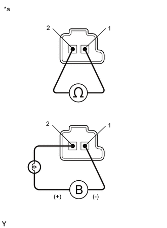
*a Component without harness connected
(Solenoid (SL1) Valve)
Remove the solenoid (SL1) valve.
-
Measure the resistance according to the value(s) in the table below.
Standard Resistance Tester Connection Condition Specified Condition Terminal 1 of the solenoid (SL1) valve - terminal 2 20°C (68°F) 5.0 to 5.6 Ω -
Connect a positive (+) lead from the battery with a 21 W bulb to terminal 2 and a negative (-) lead to terminal 1 of the solenoid valve connector. Check that the valve moves and makes an operating sound.
OK Valve moves and makes an operating sound. -
Install the solenoid (SL1) valve.
Result Proceed to OK NG
OK
REPAIR OR REPLACE TRANSMISSION WIRE Click here
NG
REPLACE SOLENOID (SL1) VALVE Click here
-