HYBRID CONTROL SYSTEM, Diagnostic DTC:P072012, P072014, P072031
| DTC Code | DTC Name |
|---|---|
| P072012 | Output Speed Sensor Circuit Short to Battery |
| P072014 | Output Speed Sensor Circuit Short to Ground or Open |
| P072031 | Output Speed Sensor No Signal |
DTC SUMMARY
-
MALFUNCTION DESCRIPTION
This DTC indicates that the ECU recognition voltage value from the transmission revolution sensor (SP2) is abnormal, or the signal (pulse) from the transmission revolution sensor (SP2) has been interrupted. The cause of this malfunction may be one of the following:
-
Open or short between transmission revolution sensor (SP2) and hybrid vehicle control ECU assembly
-
Transmission revolution sensor (SP2) malfunction
-
DESCRIPTION
The transmission revolution sensor (SP2) detects the output shaft rotation speed and sends it to the hybrid vehicle control ECU assembly.
Based on the motor resolver signal and the transmission revolution sensor (SP2) signal, the hybrid vehicle control ECU assembly controls torque and shift timing.
| DTC No. | Detection Item | DTC Detection Condition | Trouble Area | MIL | Warning Indicate |
|---|---|---|---|---|---|
| P072012 | Output Speed Sensor Circuit Short to Battery | Turn the power switch on (READY) and wait for 3 seconds or more. The transmission revolution sensor (SP2) input signal voltage is higher than 1.8 V for 4.5 seconds or more. (1-trip detection logic) |
|
Comes on | Master Warning Light: Comes on |
| P072014 | Output Speed Sensor Circuit Short to Ground or Open | Turn the power switch on (READY) and wait for 3 seconds or more. The transmission revolution sensor (SP2) input signal voltage is below 0.2 V for 4.5 seconds or more. (1-trip detection logic) |
|
Comes on | Master Warning Light: Comes on |
| P072031 | Output Speed Sensor No Signal | The transmission revolution sensor (SP2) signal is not input for 5 seconds or more when the vehicle speed is 20km/h (12.4 mph) or more and shift change is not performed. (1-trip detection logic) |
|
Comes on | Master Warning Light: Comes on |
| DTC No. | Data List |
|---|---|
| P072012 |
|
| P072014 | |
| P072031 |
*2: 0.1 to 1.9 V with engine idling when normal
CONFIRMATION DRIVING PATTERN
Tech Tips
After repair has been completed, clear the DTC and then check that the vehicle has returned to normal by performing the following All Readiness check procedure.
-
Connect the GTS to the DLC3.
-
Turn the power switch on (IG) and turn the GTS on.
-
Clear the DTCs (even if no DTCs are stored, perform the clear DTC procedure).
-
Turn the power switch off and wait for 2 minutes or more.
-
Turn the power switch on (READY) and wait for 5 seconds or more.
-
Enter the following menus: Powertrain / Hybrid Control / Utility / All Readiness.
-
Check the DTC judgment result.
Tech Tips
-
If the judgment result shows NORMAL, the system is normal.
-
If the judgment result shows ABNORMAL, the system has a malfunction.
-
If the judgment result shows INCOMPLETE or N/A, perform the normal judgment procedure again.
-
When the DTC P072012 or P072014 is output:
-
Connect the GTS to the DLC3.
-
Turn the power switch on (IG) and turn the GTS on.
-
Clear the DTCs (even if no DTCs are stored, perform the clear DTC procedure).
-
Turn the power switch off and wait for 2 minutes or more.
-
Turn the power switch on (READY).
-
Drive the vehicle at 20 km/h (12.4 mph) or more for 3 seconds or more.
-
Enter the following menus: Powertrain / Hybrid Control / Utility / All Readiness.
-
Check the DTC judgment result.
Tech Tips
-
If the judgment result shows NORMAL, the system is normal.
-
If the judgment result shows ABNORMAL, the system has a malfunction.
-
If the judgment result shows INCOMPLETE or N/A, perform the normal judgment procedure again.
-
When the DTC P072031 is output:
WIRING DIAGRAM
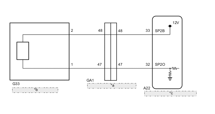
| *a | No. 1 Engine Room Relay Block Connector |
| *b | Transmission Revolution Sensor (SP2) |
| *c | Hybrid Vehicle Control ECU Assembly |
PROCEDURE
-
CHECK TRANSMISSION REVOLUTION SENSOR (SP2 TERMINAL)
-
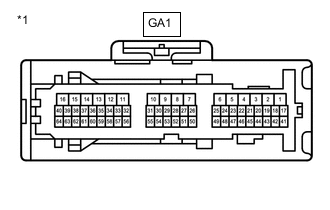
*a No. 1 Engine Room Relay Block Connector Disconnect the GA1 No. 1 engine room relay block connector.
-
Measure the resistance according to the value(s) in the table below.
Standard Resistance Tester Connection Condition Specified Condition GA1-47 - Body ground Always 99 to 101 Ω -
Turn the power switch on (IG).
-
Measure the voltage according to the value(s) in the table below.
Standard Voltage Tester Connection Condition Specified Condition GA1-48 - Body ground Power switch on (IG) 11 to 14 V -
Reconnect the GA1 No. 1 engine room relay block connector.
-
Turn the power switch off.
Result Proceed to OK NG
NG 
CHECK HARNESS AND CONNECTOR (NO. 1 ENGINE ROOM RELAY BLOCK CONNECTOR - HYBRID VEHICLE CONTROL ECU ASSEMBLY) Click here
OK 
-
-
INSPECT HARNESS AND CONNECTOR (NO. 1 ENGINE ROOM RELAY BLOCK CONNECTOR - TRANSMISSION REVOLUTION SENSOR (SP2))
-
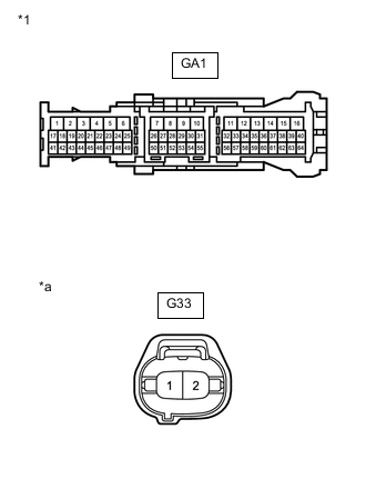
*1 No. 1 Engine Room Relay Block Connector *a Component without harness connected
(to Transmission Revolution Sensor (SP2) Connector)
Disconnect the GA1 No. 1 engine room relay block connector.
-
Disconnect the G33 transmission revolution sensor (SP2) connector.
-
Measure the resistance according to the value(s) in the table below.
Standard Resistance Tester Connection Condition Specified Condition GA1-48 - G33-2 Always Below 1 Ω GA1-47 - G33-1 Always Below 1 Ω GA1-48 or G33-2 - Body ground Always 10 kΩ or higher GA1-47 or G33-1 - Body ground Always 10 kΩ or higher -
Reconnect the G33 transmission revolution sensor (SP2) connector.
-
Reconnect the GA1 No. 1 engine room relay block connector.
Result Proceed to OK NG
OK 
REPLACE TRANSMISSION REVOLUTION SENSOR (SP2) Click here
NG
REPAIR OR REPLACE HARNESS OR CONNECTOR
-
-
CHECK HARNESS AND CONNECTOR (NO. 1 ENGINE ROOM RELAY BLOCK CONNECTOR - HYBRID VEHICLE CONTROL ECU ASSEMBLY)
-
Disconnect the A22 hybrid vehicle control ECU assembly connector.
-
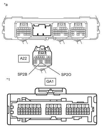
*a Rear view of wire harness connector
(to Hybrid Vehicle Control ECU Assembly)
*1 No. 1 Engine Room Relay Block Connector Disconnect the GA1 No. 1 engine room relay block connector.
-
Measure the resistance according to the value(s) in the table below.
Standard Resistance Tester Connection Condition Specified Condition A22-33 (SP2B) - GA1-48 Always Below 1 Ω A22-32 (SP2O) - GA1-47 Always Below 1 Ω A22-33 (SP2B) or GA1-48 - Body ground Always 10 kΩ or higher A22-32 (SP2O) or GA1-47 - Body ground Always 10 kΩ or higher Result Proceed to OK NG -
Reconnect the GA1 No. 1 engine room relay block connector.
-
Reconnect the A22 hybrid vehicle control ECU assembly connector.
OK
REPLACE HYBRID VEHICLE CONTROL ECU ASSEMBLY Click here
NG
REPAIR OR REPLACE HARNESS OR CONNECTOR
-