HYBRID CONTROL SYSTEM, Diagnostic DTC:P056014
| DTC Code | DTC Name |
|---|---|
| P056014 | System Voltage (BATT) Circuit Short to Ground or Open |
DESCRIPTION
Auxiliary battery power is supplied to the BATT terminal of the hybrid vehicle control ECU assembly in order to store DTCs and freeze frame data. Even if the power switch is turned off, back-up power is supplied.
| DTC No. | Detection Item | DTC Detection Condition | Trouble Area | MIL | Warning Indicate |
|---|---|---|---|---|---|
| P056014 | System Voltage (BATT) Circuit Short to Ground or Open | Malfunction in the hybrid vehicle control ECU assembly back-up power source circuit (1 trip detection logic) |
|
Comes on | Master Warning Light: Comes on |
CONFIRMATION DRIVING PATTERN
Tech Tips
After repair has been completed, clear the DTC and then check that the vehicle has returned to normal by performing the following All Readiness check procedure.
-
Connect the GTS to the DLC3.
-
Turn the power switch on (IG) and turn the GTS on.
-
Clear the DTCs (even if no DTCs are stored, perform the clear DTC procedure).
-
Turn the power switch off and wait for 2 minutes or more.
-
Turn the power switch on (IG) and turn the GTS on.
-
With power switch on (IG) and wait for 5 seconds or more.
-
Enter the following menus: Powertrain / Hybrid Control / Utility / All Readiness.
-
Check the DTC judgment result.
Tech Tips
-
If the judgment result shows NORMAL, the system is normal.
-
If the judgment result shows ABNORMAL, the system has a malfunction.
-
If the judgment result shows INCOMPLETE or N/A, perform the normal judgment procedure again.
-
WIRING DIAGRAM
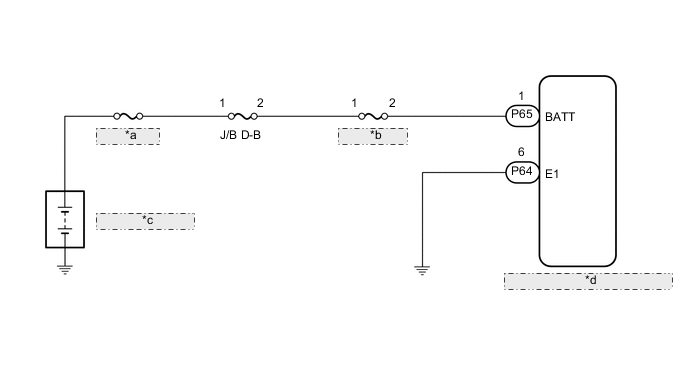
| *a | R/B RR NO.1 |
| *b | ECU-B D NO.1 |
| *c | Auxiliary Battery |
| *d | Hybrid Vehicle Control ECU Assembly |
PROCEDURE
-
CHECK CONNECTOR CONNECTION CONDITION (HYBRID VEHICLE CONTROL ECU ASSEMBLY CONNECTOR)
-
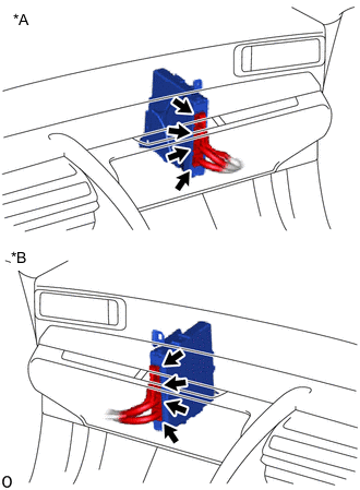
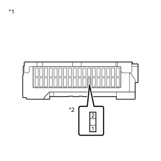
*A for LHD *B for RHD Check the connector connections and contact pressure of the relevant terminals for the hybrid vehicle control ECU assembly connectors.
OK The connectors are connected securely and there are no contact pressure problems. Result Proceed to OK NG
NG 
CONNECT SECURELY
OK 
-
-
CHECK HARNESS AND CONNECTOR (HYBRID VEHICLE CONTROL ECU ASSEMBLY - ECU-B D NO.1 FUSE)
-
Turn the power switch off.
-
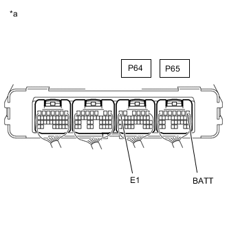
*a Component with harness connected
(Hybrid Vehicle Control ECU Assembly)
Measure the voltage according to the value(s) in the table below.
Standard Voltage Tester Connection Condition Specified Condition P65-1 (BATT) - P64-6 (E1) Power switch off 11 to 14 V Result Proceed to OK NG
OK
REPLACE HYBRID VEHICLE CONTROL ECU ASSEMBLY Click here
NG
-
-
CHECK FUSE (ECU-B D NO.1)
-
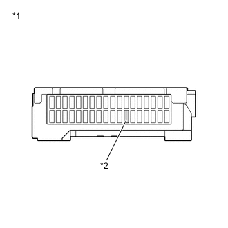
*1 Driver Side Junction Block Assembly *2 ECU-B D NO.1 Fuse Remove the ECU-B D NO.1 Fuse from the driver side junction block assembly.
-
Check if there is an open circuit in the ECU-B D NO.1 Fuse in the driver side junction block assembly.
OK There is no open circuit in the ECU-B D NO.1 Fuse. -
Install the ECU-B D NO.1 Fuse.
Result Proceed to OK NG
NG
REPLACE FUSE (ECU-B D NO.1)
OK
-
-
CHECK HARNESS AND CONNECTOR (ECU-B D NO.1 FUSE - BATTERY TERMINAL)
-
Remove the ECU-B D NO.1 fuse from the driver side junction block assembly.
-
Disconnect the cable from the negative (-) auxiliary battery terminal.
-
Disconnect the cable from the positive (+) auxiliary battery terminal.
-
*1 Driver Side Junction Block Assembly *2 ECU-B D NO.1 Fuse Measure the resistance according to the value(s) in the table below.
Standard Resistance Tester Connection Condition Specified Condition 1 - Auxiliary battery positive (+) cable Power switch off Below 1 Ω 1 - Body ground Power switch off 10 kΩ or higher -
Connect the cable to the positive (+) auxiliary battery terminal.
-
Connect the cable to the negative (-) auxiliary battery terminal.
-
Install the ECU-B D NO.1 fuse.
Result Proceed to OK NG
NG
REPAIR OR REPLACE HARNESS OR CONNECTOR
OK
-
-
CHECK HARNESS AND CONNECTOR (ECU-B D NO.1 FUSE - HYBRID VEHICLE CONTROL ECU ASSEMBLY)
-
Remove the ECU-B D NO.1 fuse from the driver side junction block assembly.
-
Disconnect the P65 hybrid vehicle control ECU assembly connector.
-
Measure the resistance according to the value(s) in the table below.
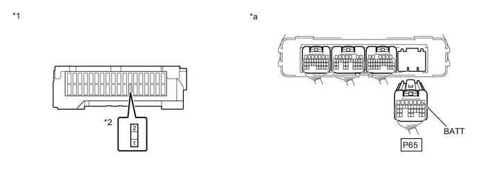
*1 Driver Side Junction Block Assembly *2 ECU-B D NO.1 Fuse *a Rear view of wire harness connector
(to Hybrid Vehicle Control ECU Assembly)
- - Standard Resistance Tester Connection Condition Specified Condition 2 (ECU-B D NO.1 fuse terminal) - P65-1 (BATT) Power switch off Below 1 Ω -
Reconnect the P65 hybrid vehicle control ECU assembly connector.
-
Install the ECU-B D NO.1 fuse.
Result Proceed to OK NG
OK
REPLACE HYBRID VEHICLE CONTROL ECU ASSEMBLY Click here
NG
REPAIR OR REPLACE HARNESS OR CONNECTOR
-