TELEMATICS SYSTEM(for G-BOOK) Emergency Call Switch Illumination Circuit
WIRING DIAGRAM
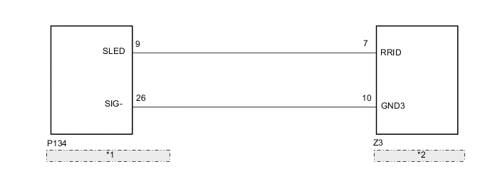
| *1 | Telephone Transceiver Assembly |
| *2 | Map Light Sub-assembly |
CAUTION / NOTICE / HINT
Note
-
Depending on the parts that are replaced during vehicle inspection or maintenance, performing initialization, registration or calibration may be needed. Refer to Precaution for G-BOOK.
-
When replacing the telephone transceiver assembly, make sure to replace it with a new one.
PROCEDURE
-
CHECK HARNESS AND CONNECTOR (TELEPHONE TRANSCEIVER ASSEMBLY - MAP LIGHT SUB-ASSEMBLY)
-
Disconnect the P134 telephone transceiver assembly connector.
-
Disconnect the Z3 map light sub-assembly connector.
-
Measure the resistance according to the value(s) in the table below.
Standard Resistance Tester Connection Condition Specified Condition P134-9 (SLED) - Z3-7 (RRID) Always Below 1 Ω P134-26 (SIG-) - Z3-10 (GND3) Always Below 1 Ω P134-9 (SLED) - Body ground Always 10 kΩ or higher P134-26 (SIG-) - Body ground Always 10 kΩ or higher Result Proceed to OK NG
NG 
REPAIR OR REPLACE HARNESS OR CONNECTOR
OK 
-
-
INSPECT MAP LIGHT SUB-ASSEMBLY
-
Remove the map light sub-assembly.
-
Connect 4 1.5 V dry-cell batteries in series.
-
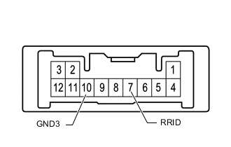
Connect a positive lead from the batteries to terminal 7 (RRID), and a negative lead to terminal 10 (GND3) of the map light sub-assembly connector.
-
Check if the illumination for the emergency call switch comes on.
OK Illumination for the emergency call switch comes on. Result Proceed to OK NG
OK
REPLACE TELEPHONE TRANSCEIVER ASSEMBLY Click here
NG
REPLACE MAP LIGHT SUB-ASSEMBLY Click here
-