WINDOW DEFOGGER SYSTEM Rear Window Defogger System does not Operate
DESCRIPTION
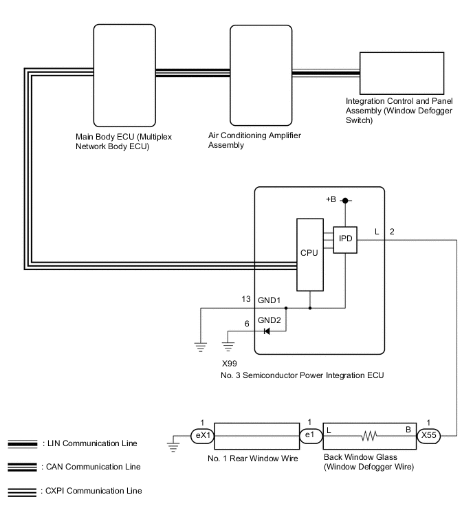
An operation request signal is sent to the air conditioning amplifier assembly via LIN communication when the integration control and panel assembly (window defogger switch) is operated.
When the air conditioning amplifier assembly receives the signal, it sends an operation request signal via CAN communication to the main body ECU (multiplex network body ECU).
When the main body ECU (multiplex network body ECU) receives the signal, it sends an operation request signal via CPXI communication to the No. 3 semiconductor power integration ECU.
After the operation request signal is received by the No. 3 semiconductor power integration ECU it outputs an operation signal and operates the window defogger.
WIRING DIAGRAM
CAUTION / NOTICE / HINT
Note
-
The window defogger system uses the CAN communication system. Inspect the communication function by following How to Proceed with Troubleshooting. Troubleshoot the window defogger system after confirming that the communication system is functioning properly.
-
The window defogger system uses the CXPI communication system. Inspect the communication function by following How to Proceed with Troubleshooting. Troubleshoot the window defogger system after confirming that the communication system is functioning properly.
-
The window defogger system is controlled by the power integration system. Troubleshoot by checking if there are any malfunctions in the power integration system by following the steps in "How to Proceed with Troubleshooting".
-
If the battery voltage becomes low, window defogger operation is canceled to prioritize supplying power to the power steering system.
-
With the negative (-) battery terminal connected, disconnect/do not connect the connector of the No. 3 semiconductor power integration ECU.
-
When replacing the No. 3 semiconductor power integration ECU, the system may not operate normally if the same part number is not used.
-
After turning the engine switch off, waiting time may be required before disconnecting the cable from the negative (-) battery terminal. Therefore, make sure to read the disconnecting the cable from the negative (-) battery terminal notices before proceeding with work.
-
When disconnecting the cable from the negative (-) battery terminal while performing repairs, some systems need to be initialized after the cable is reconnected.
PROCEDURE
-
CHECK AIR CONDITIONING SYSTEM
-
Check the air conditioning system.
Tech Tips
Both the window defogger system operation signal and air conditioning system operation signal are transmitted to the air conditioning amplifier assembly via the same communication line.
OK The air conditioning system operates normally. Result Proceed to OK NG
NG 
GO TO AIR CONDITIONING SYSTEM Click here
OK 
-
-
CHECK INTEGRATION CONTROL AND PANEL ASSEMBLY
-
Check that the defogger indicator illuminates when the window defogger switch is on.
OK Defogger indicator illuminates. Result Proceed to OK NG
NG
REPLACE INTEGRATION CONTROL AND PANEL ASSEMBLY Click here
OK
-
-
PERFORM ACTIVE TEST USING GTS (DEFOGGER RELAY (REAR))
-
Using the GTS, perform the Active Test.
Body Electrical > Air Conditioner > Active TestTester Display Measurement Item Control Range Diagnostic Note Defogger Relay (Rear) Back window glass (window defogger wire) OFF or ON -
Body Electrical > Air Conditioner > Active TestTester Display Defogger Relay (Rear) OK Back window glass (window defogger wire) warms up. Result Proceed to OK NG
NG 
READ VALUE USING GTS (STATUS OF REAR DEFOGGER FUSE) Click here
OK
-
-
CHECK AIR CONDITIONING AMPLIFIER ASSEMBLY
-
Temporarily replace the air conditioning amplifier assembly with a new or normally functioning one.
-
Check that the window defogger system operates normally.
OK The window defogger system operates normally. Result Proceed to OK NG
OK
END (AIR CONDITIONING AMPLIFIER ASSEMBLY IS DEFECTIVE)
NG
REPLACE INTEGRATION CONTROL AND PANEL ASSEMBLY Click here
-
-
READ VALUE USING GTS (STATUS OF REAR DEFOGGER FUSE)
-
Using the GTS, read the Data List.
Body Electrical > Power Integration No.3 > Data ListTester Display Measurement Item Range Normal Condition Diagnostic Note Status of Rear Defogger Fuse Rear defogger fuse condition Disconnect or Connect Disconnect: Fuse shut off
Connect: Fuse not shut off
-
Body Electrical > Power Integration No.3 > Data ListTester Display Status of Rear Defogger Fuse OK The Data List value displays "Connect". Result Proceed to OK NG
NG
CHECK BACK WINDOW GLASS (WINDOW DEFOGGER WIRE) Click here
OK
-
-
READ VALUE USING GTS (REAR DEFOGGER INPUT SIGNAL)
-
Using the GTS, read the Data List.
Body Electrical > Power Integration No.3 > Data ListTester Display Measurement Item Range Normal Condition Diagnostic Note Rear Defogger Input Signal Rear defogger input condition ON or OFF ON: Rear defogger operates
OFF: Rear defogger does not operate
-
Body Electrical > Power Integration No.3 > Data ListTester Display Rear Defogger Input Signal OK The Data List value displays "ON" with the integration control and panel assembly (window defogger switch) set to ON. Result Proceed to OK NG
NG
REPLACE AIR CONDITIONING AMPLIFIER ASSEMBLY Click here
OK
-
-
READ VALUE USING GTS (REAR DEFOGGER OUTPUT SIGNAL)
-
Using the GTS, read the Data List.
Body Electrical > Power Integration No.3 > Data ListTester Display Measurement Item Range Normal Condition Diagnostic Note Rear Defogger Output Signal Rear defogger output condition ON or OFF ON: Rear defogger is on
OFF: Rear defogger is off
-
Body Electrical > Power Integration No.3 > Data ListTester Display Rear Fog Light Output Signal OK The Data List value displays "ON" with the integration control and panel assembly (window defogger switch) set to ON. Result Proceed to OK NG
NG
REPLACE NO. 3 SEMICONDUCTOR POWER INTEGRATION ECU Click here
OK
-
-
CHECK NO. 3 SEMICONDUCTOR POWER INTEGRATION ECU
-
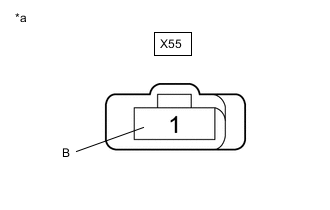
*a Front view of wire harness connector
(to Back Window Glass [Window Defogger Wire])
Disconnect the back window glass (window defogger wire) connector.
-
Measure the voltage according to the value(s) in the table below.
Standard Voltage Tester Connection Switch Condition Specified Condition X55-1 (B) - Body ground Engine switch on (IG), window defogger switch on 8 V or higher Engine switch on (IG), window defogger switch off Below 3 V Result Proceed to OK NG
NG
CHECK HARNESS AND CONNECTOR (NO. 3 SEMICONDUCTOR POWER INTEGRATION ECU - BACK WINDOW GLASS [WINDOW DEFOGGER WIRE]) Click here
OK
-
-
INSPECT NO. 1 REAR WINDOW WIRE
-
Remove the No. 1 rear window wire.
-
Inspect the No. 1 rear window wire.
Result Proceed to OK NG
NG
REPLACE NO. 1 REAR WINDOW WIRE Click here
OK
-
-
CHECK HARNESS AND CONNECTOR (NO. 1 REAR WINDOW WIRE - BODY GROUND)
-
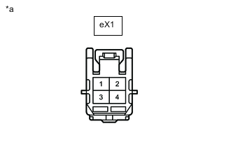
*a Front view of wire harness connector
(to No. 1 Rear Window Wire)
Disconnect the No. 1 rear window wire connector.
-
Measure the resistance according to the value(s) in the table below.
Standard Resistance Tester Connection Condition Specified Condition eX1-1 - Body ground Always Below 1 Ω Result Proceed to OK NG
OK
REPAIR BACK WINDOW GLASS (WINDOW DEFOGGER WIRE) Click here
NG
REPAIR OR REPLACE HARNESS OR CONNECTOR
-
-
CHECK HARNESS AND CONNECTOR (NO. 3 SEMICONDUCTOR POWER INTEGRATION ECU - BACK WINDOW GLASS [WINDOW DEFOGGER WIRE])
-
Turn the engine switch off.
-
Disconnect the cable from the negative (-) battery terminal.
-
Disconnect the X99 No. 3 semiconductor power integration ECU connector.
-
Disconnect the X55 back window glass (window defogger wire) connector.
-
Measure the resistance according to the value(s) in the table below.
Standard Resistance Tester Connection Condition Specified Condition X99-2 (L) - X55-1 (B) Always Below 1 Ω Result Proceed to OK NG
OK
REPLACE NO. 3 SEMICONDUCTOR POWER INTEGRATION ECU Click here
NG
REPAIR OR REPLACE HARNESS OR CONNECTOR
-
-
CHECK BACK WINDOW GLASS (WINDOW DEFOGGER WIRE)
-
Disconnect the X55 back window glass (window defogger wire) connector.
-
Turn the window defogger switch "OFF" on the integration control and panel assembly.
-
Turn the window defogger switch "ON" on the integration control and panel assembly.
-
Using the GTS, read the Data List.
Body Electrical > Power Integration No.3 > Data ListTester Display Measurement Item Range Normal Condition Diagnostic Note Status of Rear Defogger Fuse Rear defogger fuse condition Disconnect or Connect Disconnect: Fuse shut off
Connect: Fuse not shut off
-
Body Electrical > Power Integration No.3 > Data ListTester Display Status of Rear Defogger Fuse OK The Data List value displays "Connect". Result Proceed to OK NG
OK
REPLACE BACK WINDOW GLASS (WINDOW DEFOGGER WIRE) Click here
NG
-
-
CHECK HARNESS AND CONNECTOR (NO. 3 SEMICONDUCTOR POWER INTEGRATION ECU - BACK WINDOW GLASS [WINDOW DEFOGGER WIRE])
-
Turn the engine switch off.
-
Disconnect the cable from the negative (-) battery terminal.
-
Disconnect the X99 No. 3 semiconductor power integration ECU connector.
-
Disconnect the X55 back window glass (window defogger wire) connector.
-
Measure the resistance according to the value(s) in the table below.
Standard Resistance Tester Connection Condition Specified Condition X99-2 (L) or X55-1 (B) - Body ground Always 10 kΩ or higher Result Proceed to OK NG
OK
REPLACE NO. 3 SEMICONDUCTOR POWER INTEGRATION ECU Click here
NG
REPAIR OR REPLACE HARNESS OR CONNECTOR
-