BRAKE MASTER CYLINDER(for LHD) INSTALLATION
PROCEDURE
-
INSTALL BRAKE MASTER CYLINDER GASKET
-
Install a new brake master cylinder gasket to the brake master with stroke simulator cylinder assembly.
-
-
INSTALL BRAKE MASTER WITH STROKE SIMULATOR CYLINDER ASSEMBLY
-
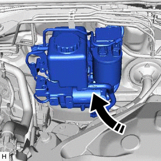
Temporarily install the brake master with stroke simulator cylinder assembly to the body.
Note
-
Do not kink or damage the No. 2 brake actuator tube.
-
Protect the surface of the relay block so that it does not become damaged on the brake master with stroke simulator cylinder assembly.
-
-
Attach the wire harness clamp.
-
Connect the brake fluid level warning switch connector.
-
Install the brake master with stroke simulator cylinder assembly with the 4 nuts.
- Torque:
- 12.7 N*m { 130 kgf*cm, 9 ft.*lbf }
-
-
INSTALL PUSH ROD PIN
-
INSTALL STOP LIGHT SWITCH ASSEMBLY
-
INSTALL BRAKE PEDAL RETURN SPRING
-
INSTALL HEATER TO REGISTER CENTER SUB DUCT
-
INSTALL NO. 2 AIR DUCT
-
INSTALL LOWER NO. 1 INSTRUMENT PANEL AIRBAG ASSEMBLY
-
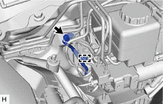
CONNECT BRAKE TUBE
-
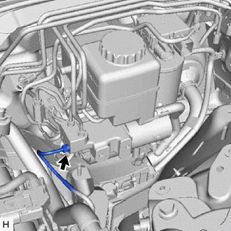
Using a union nut wrench, connect the brake tube to the brake master with stroke simulator cylinder assembly.
- Torque:
- Specified tightening torque
- 15.2 N*m { 155 kgf*cm, 11 ft.*lbf }
Note
-
Do not kink or damage the brake tube.
-
Do not allow any foreign matter such as dirt or dust to enter the brake tube from the connecting parts.
Tech Tips
-
Calculate the torque wrench reading when changing the fulcrum length of the torque wrench.
-
When using a union nut wrench (fulcrum length of 22 mm (0.8661 in.)) + torque wrench (fulcrum length of 162 mm (6.3779 in.)): 13.4 N*m (137 kgf*cm, 10 ft.*lbf)
-
-
INSTALL BRAKE ACTUATOR WITH BRACKET
-
CONNECT CABLE TO NEGATIVE BATTERY TERMINAL
-
BLEED BRAKE SYSTEM
-
INSPECT AND ADJUST BRAKE PEDAL
-
INSPECT FOR BRAKE FLUID LEAK
-
READ VALUE OF ACCUMULATOR PRESSURE SENSOR OUTPUT VOLTAGE
Tech Tips
If removing and installing the No. 2 brake actuator tube, check for a brake fluid leak from the No. 2 brake actuator tube connection area by monitoring the accumulator pressure sensor output value from the brake actuator. Directly checking for a brake fluid leak from the No. 2 brake actuator tube connection area is difficult.
-
Turn the engine switch off.
-
Connect the GTS to the DLC3.
-
Turn the engine switch on (IG).
-
Operate the GTS according to the display and select "DATA LIST".
Chassis > ABS/VSC/TRAC > Data ListTester Display Accumulator Sensor Skid control ECU Tester Display Measurement Item/Range Normal Condition Diagnostic Note Accumulator Pressure Sensor Accumulator pressure sensor / min.: 0 V, max.: 5 V Specified value: 2.6 to 3.8 V - -
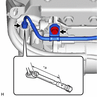
*a Torque Wrench Fulcrum Length Depress the brake pedal 4 or 5 times to operatethe pump motor, and check the output value on the GTS with the motor stopped (not braking).
OK Accumulator pressure sensor's output voltage drops 0.2 V or less for 30 seconds. If the voltage drops more than 0.2 V, there may be a brake fluid leak from the No. 2 brake actuator tube connection area. Remove the brake actuator and brake accumulator pump, and then repeat the procedures above from the retightening of the 2 union nuts of the No. 2 brake actuator tube.
- Torque:
- Specified tightening torque
- 15.2 N*m { 155 kgf*cm, 11 ft.*lbf }
Tech Tips
-
Calculate the torque wrench reading when changing the fulcrum length of the torque wrench.
-
When using a union nut wrench (fulcrum length of 22 mm (0.8661 in.)) + torque wrench (fulcrum length of 162 mm (6.3779 in.)): 13.4 N*m (137 kgf*cm, 10 ft.*lbf)
-
-
CHECK BRAKE MASTER CYLINDER WITH GTS
-
CHECK MASTER CYLINDER PRESSURE SENSOR SIGNAL