ELECTRONICALLY CONTROLLED BRAKE SYSTEM, Diagnostic DTC:C1380/15
| DTC Code | DTC Name |
|---|---|
| C1380/15 | Stop Light Control Relay Malfunction |
DESCRIPTION
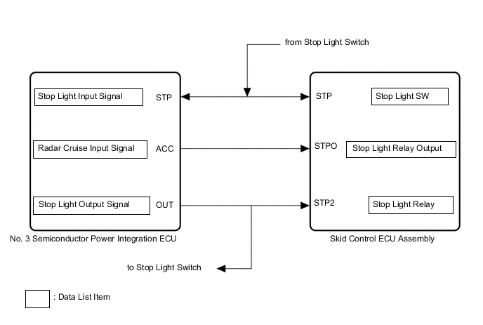
When the brake hold system or dynamic radar cruise control system operates, the skid control ECU assembly turns ON the stop light drive output (STPO) to operate the No. 3 semiconductor power integration ECU and illuminate the stop light.
| DTC No. | Detection Item | INF Code | DTC Detection Condition | Trouble Area | Note |
|---|---|---|---|---|---|
| C1380/15 | Stop Light Control Relay Malfunction | 391 392 |
|
|
Brake hold DTC |
| DTC No. | Brake warning light / yellow (minor malfunction) display code | ABS warning light display code | Slip indicator light display code | Brake hold standby indicator light display code |
|---|---|---|---|---|
| C1380 | - | - | - | 15 |
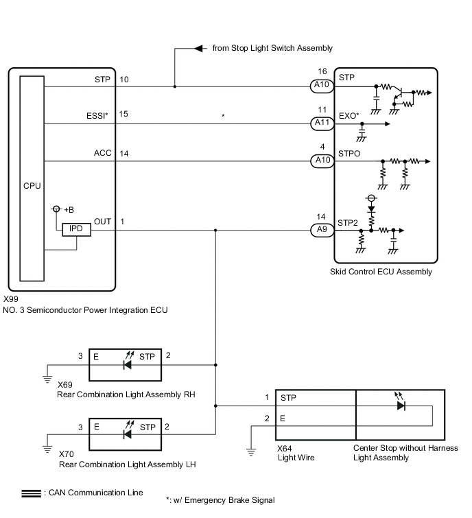
WIRING DIAGRAM
CAUTION / NOTICE / HINT
Note
-
When replacing the skid control ECU assembly, perform initialization and calibration of the linear solenoid valve.
-
Inspect the fuses for circuits related to this system before performing the following procedure.
PROCEDURE
-
CHECK FOR DTCs (POWER INTEGRATION SYSTEM)
-
Check for DTCs.
Body Electrical > Power Integration No.3 > Trouble CodesTech Tips
If there is a malfunction in the No. 3 semiconductor power integration ECU, integration relay system DTCs may also have been detected. Check the integration relay system first.
Result Result Proceed to Power integration system DTCs are not output A Power integration system DTCs are output B
B 
GO TO POWER INTEGRATION SYSTEM Click here
A 
-
-
READ VALUE USING GTS (STOP LIGHT INPUT SIGNAL, STOP LIGHT OUTPUT SIGNAL, STOP LIGHT SW AND STOP LIGHT RELAY)
-
Using the GTS, check the Data List "Stop Light Input Signal", "Stop Light Output Signal", "Stop Light SW" and "Stop Light Relay" with the brake pedal operated.
Body Electrical > Power Integration No.3 > Data ListTester Display Measurement Item Range Normal Condition Diagnostic Note Stop Light Input Signal Stop light switch assembly input condition ON or OFF OFF: Brake pedal released
ON: Brake pedal depressed
- Stop Light Output Signal Stop light output condition ON or OFF ON: Stop light is on
OFF: Stop light is off
Stop lights blink during emergency brake signal control
Body Electrical > Power Integration No.3 > Data ListTester Display Stop Light Input Signal Stop Light Output Signal
Chassis > ABS/VSC/TRC > Data ListTester Display Measurement Item Range Normal Condition Diagnostic Note Stop Light SW Stop light switch assembly ON or OFF ON: Brake pedal depressed
OFF: Brake pedal released
- Stop Light Relay No. 3 Semiconductor power integration ECU (STP2 terminal input) ON or OFF ON: Brake pedal depressed
OFF: Brake pedal released
-
Chassis > ABS/VSC/TRC > Data ListTester Display Stop Light SW Stop Light Relay OK Brake pedal operation Data List Display Condition No. 3 Semiconductor Power Integration ECU Skid Control ECU Assembly Stop Light Input Signal Stop Light Output Signal Stop Light Switch Stop Light Relay Brake pedal depressed ON ON ON ON Result Brake pedal operation Data List Display Condition Result No. 3 Semiconductor Power Integration ECU Skid Control ECU Assembly Stop Light Input Signal Stop Light Output Signal Stop Light Switch Stop Light Relay Brake pedal depressed ON ON ON ON A ON ON OFF ON B ON OFF ON OFF C ON ON ON OFF D OFF OFF ON OFF E
B 
CHECK HARNESS AND CONNECTOR (SKID CONTROL ECU ASSEMBLY - NO. 3 SEMICONDUCTOR POWER INTEGRATION ECU) Click here
C
READ VALUE USING GTS (STOP LIGHT OUTPUT SIGNAL AND STATUS OF STOP LIGHT FUSE) Click here
D
CHECK HARNESS AND CONNECTOR (STPO TERMINAL) Click here
E
CHECK HARNESS AND CONNECTOR (SKID CONTROL ECU ASSEMBLY - NO. 3 SEMICONDUCTOR POWER INTEGRATION ECU) Click here
A
-
-
READ VALUE USING GTS (STOP LIGHT INPUT SIGNAL, STOP LIGHT OUTPUT SIGNAL, STOP LIGHT SW AND STOP LIGHT RELAY)
-
Using the GTS, check the Data List "Stop Light Input Signal", "Stop Light Output Signal", "Stop Light SW" and "Stop Light Relay" with the brake pedal operated.
Body Electrical > Power Integration No.3 > Data ListTester Display Measurement Item Range Normal Condition Diagnostic Note Stop Light Input Signal Stop light switch assembly input condition ON or OFF ON: Brake pedal depressed
OFF: Brake pedal released
- Stop Light Output Signal Stop light output condition ON or OFF ON: Stop light is on
OFF: Stop light is off
Stop lights blink during emergency brake signal control
Body Electrical > Power Integration No.3 > Data ListTester Display Stop Light Input Signal Stop Light Output Signal
Chassis > ABS/VSC/TRC > Data ListTester Display Measurement Item Range Normal Condition Diagnostic Note Stop Light SW Stop light switch assembly ON or OFF ON: Brake pedal depressed
OFF: Brake pedal released
- Stop Light Relay No. 3 Semiconductor power integration ECU (STP2 terminal input) ON or OFF ON: Brake pedal depressed
OFF: Brake pedal released
-
Chassis > ABS/VSC/TRC > Data ListTester Display Stop Light SW Stop Light Relay OK Brake pedal operation Data List Display Condition No. 3 Semiconductor Power Integration ECU Skid Control ECU Assembly Stop Light Input Signal Stop Light Output Signal Stop Light Switch Stop Light Relay Brake pedal depressed OFF OFF OFF OFF Result Brake pedal operation Data List Display Condition Result No. 3 Semiconductor Power Integration ECU Skid Control ECU Assembly Stop Light Input Signal Stop Light Output Signal Stop Light Switch Stop Light Relay Brake pedal depressed OFF OFF OFF OFF A OFF ON OFF ON B
B
READ VALUE USING GTS (RADAR CRUISE INPUT SIGNAL, STOP LIGHT OUTPUT SIGNAL, STOP LIGHT RELAY AND STOP LIGHT RELAY OUTPUT) Click here
A
-
-
PERFORM ACTIVE TEST USING GTS (STOP LIGHT RELAY)
-
Enter the following menus: Chassis / ABS/VSC/TRC / Active Test.
-
Perform "Active Test" according to the display on the GTS.
Chassis > ABS/VSC/TRC > Active TestTester Display Measurement Item Restrict Condition Diagnostic Note Stop Light Relay No. 3 Semiconductor power integration ECU ECU (Stop light output) ON/OFF Stop lights come on
Chassis > ABS/VSC/TRC > Data ListTester Display Measurement Item Range Normal Condition Diagnostic Note Stop Light SW Stop light switch assembly ON or OFF ON: Brake pedal depressed
OFF: Brake pedal released
- Stop Light Relay No. 3 Semiconductor power integration ECU (STP2 terminal input) ON or OFF ON: Brake pedal depressed
OFF: Brake pedal released
-
Body Electrical > Power Integration No.3 > Data ListTester Display Measurement Item Range Normal Condition Diagnostic Note Radar Cruise Input Signal Radar cruise operation condition ON or OFF ON: Radar cruise system operates
OFF: Radar cruise system does not operate
- Stop Light Output Signal Stop light output condition Stop light output condition ON: Stop light is on
OFF: Stop light is off
Stop lights blink during emergency brake signal control
Chassis > ABS/VSC/TRC > Active TestActive Test Display Stop Light Relay Body Electrical > Power Integration No.3 > Dual Data ListData List Display Stop Light Relay Stop Light Relay Output Data List Display Radar Cruise Input Signal Stop Light Output Signal OK Active Test Condition Data List Display Condition
Stop Light Relay
Stop Light Relay No. 3 Semiconductor Power Integration ECU Skid Control ECU Assembly Stop Light Input Signal Stop Light Output Signal Stop Light Switch Stop Light Relay ON ON ON ON ON Result Active Test Condition Data List Display Condition Result Stop Light Relay Skid Control ECU Assembly No. 3 Semiconductor Power Integration ECU Stop Light Relay Stop Light Relay Output Radar Cruise Input Signal Stop Light Output Signal ON ON ON ON ON A OFF ON ON OFF B OFF OFF OFF OFF C
B
REPLACE NO. 3 SEMICONDUCTOR POWER INTEGRATION ECU Click here
C
CHECK HARNESS AND CONNECTOR (SKID CONTROL ECU ASSEMBLY - NO. 3 SEMICONDUCTOR POWER INTEGRATION ECU) Click here
A
-
-
RECONFIRM DTC
-
Clear the DTCs.
Chassis > ABS/VSC/TRC > Clear DTCs -
Perform "Active Test" according to the display on the GTS.
Chassis > ABS/VSC/TRC > Active TestTester Display Measurement Item Restrict Condition Diagnostic Note Stop Light Relay No. 3 Semiconductor power integration ECU ECU (Stop light output) ON/OFF Stop lights come on
Chassis > ABS/VSC/TRC > Active TestTester Display Stop Light Relay Note
Perform the Active Test "Stop Light Relay" for 2 seconds or more.
Tech Tips
By performing the Active Test, DTCs can be detected.
-
Check if the same DTC is output.
Chassis > ABS/VSC/TRC > Trouble CodesResult Result Proceed to DTC C1380/15 is not output. A DTC C1380/15 is output. B
A
USE SIMULATION METHOD TO CHECK Click here
B
REPLACE SKID CONTROL ECU ASSEMBLY for RHD: Click here
REPLACE SKID CONTROL ECU ASSEMBLY for LHD: Click here -
-
CHECK HARNESS AND CONNECTOR (SKID CONTROL ECU ASSEMBLY - NO. 3 SEMICONDUCTOR POWER INTEGRATION ECU)
-
Disconnect the A10 skid control ECU assembly connector.
-
Disconnect the X99 No. 3 semiconductor power integration ECU connector.
-
Measure the resistance according to the value(s) in the table below.
Standard Resistance Tester Connection Condition Specified Condition A10-16 (STP) - X99-10 (STP) Always Below 1 Ω A10-16 (STP) or X99-10(STP) - Body ground Always 10 kΩ or higher Result Proceed to OK NG
OK
REPLACE SKID CONTROL ECU ASSEMBLY for RHD: Click here
REPLACE SKID CONTROL ECU ASSEMBLY for LHD: Click hereNG
REPAIR OR REPLACE HARNESS OR CONNECTOR
-
-
READ VALUE USING GTS (RADAR CRUISE INPUT SIGNAL, STOP LIGHT OUTPUT SIGNAL, STOP LIGHT RELAY AND STOP LIGHT RELAY OUTPUT)
-
Using the GTS, check the Data List "Radar Cruise Input Signal", "Stop Light Output Signal", "Stop Light Relay" and "Stop Light Relay Output" with the brake pedal operated.
Body Electrical > Power Integration No.3 > Data ListTester Display Measurement Item Range Normal Condition Diagnostic Note Radar Cruise Input Signal Radar cruise operation condition ON or OFF ON: Radar cruise system operates
OFF: Radar cruise system does not operate
- Stop Light Output Signal Stop light output condition ON or OFF ON: Stop light is on
OFF: Stop light is off
Stop lights blink during emergency brake signal control
Body Electrical > Power Integration No.3 > Data ListTester Display Radar Cruise Input Signal Stop Light Output Signal
Chassis > ABS/VSC/TRC > Data ListTester Display Measurement Item Range Normal Condition Diagnostic Note Stop Light Relay No. 3 Semiconductor power integration ECU (STP2 terminal input) ON or OFF ON: Brake pedal depressed
OFF: Brake pedal released
- Stop Light Relay Output No. 3 Semiconductor power integration ECU (STPO terminal input) ON or OFF ON: Output on
OFF: Output off
-
Chassis > ABS/VSC/TRC > Data ListTester Display Stop Light Relay Stop Light Relay Output OK Brake pedal operation Data List Display Condition No. 3 Semiconductor Power Integration ECU Skid Control ECU Assembly Stop Light Input Signal Stop Light Output Signal Stop Light Switch Stop Light Relay Brake pedal depressed OFF OFF OFF OFF Result Brake pedal operation Data List Display Condition Result No. 3 Semiconductor Power Integration ECU Skid Control ECU Assembly Stop Light Input Signal Stop Light Output Signal Stop Light Switch Stop Light Relay Brake pedal depressed ON ON ON ON A ON ON ON OFF B OFF ON ON OFF C
A
REPLACE SKID CONTROL ECU ASSEMBLY for RHD: Click here
REPLACE SKID CONTROL ECU ASSEMBLY for LHD: Click hereC
REPLACE NO. 3 SEMICONDUCTOR POWER INTEGRATION ECU Click here
B
-
-
CHECK HARNESS AND CONNECTOR (SKID CONTROL ECU ASSEMBLY - NO. 3 SEMICONDUCTOR POWER INTEGRATION ECU)
-
Disconnect the A10 skid control ECU assembly connector.
-
Disconnect the X99 No. 3 semiconductor power integration ECU connector.
-
Measure the resistance according to the value(s) in the table below.
Standard Resistance Tester Connection Condition Specified Condition A10-4 (STPO) - X99-14 (ACC) Always Below 1 Ω A10-4 (STPO) or X99-14 (ACC) - Body ground Always 10 kΩ or higher Result Proceed to OK NG
OK
REPLACE NO. 3 SEMICONDUCTOR POWER INTEGRATION ECU Click here
NG
REPAIR OR REPLACE HARNESS OR CONNECTOR
-
-
CHECK HARNESS AND CONNECTOR (SKID CONTROL ECU ASSEMBLY - NO. 3 SEMICONDUCTOR POWER INTEGRATION ECU)
-
Disconnect the A10 skid control ECU assembly connector.
-
Disconnect the X99 No. 3 semiconductor power integration ECU connector.
-
Measure the resistance according to the value(s) in the table below.
Standard Resistance Tester Connection Condition Specified Condition A10-4 (STPO) - X99-14 (ACC) Always Below 1 Ω A10-4 (STPO) or X99-14 (ACC) - Body ground Always 10 kΩ or higher Result Proceed to OK NG
NG
REPAIR OR REPLACE HARNESS OR CONNECTOR
OK
-
-
CHECK HARNESS AND CONNECTOR (STPO TERMINAL)
-
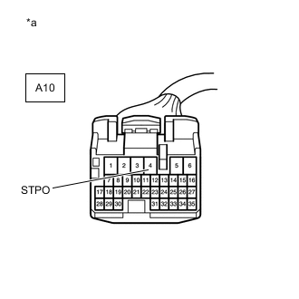
*a Front view of wire harness connector
(to Skid Control ECU Assembly)
Disconnect the A10 skid control ECU assembly connector.
-
Measure the voltage according to the value(s) in the table below.
Standard Voltage Tester Connection Condition Specified Condition A10-4 (STPO) - Body ground Engine switch on (IG) 11 to 14 V Result Proceed to OK NG
OK
REPLACE SKID CONTROL ECU ASSEMBLY for RHD: Click here
REPLACE SKID CONTROL ECU ASSEMBLY for LHD: Click hereNG
REPLACE NO. 3 SEMICONDUCTOR POWER INTEGRATION ECU Click here
-
-
READ VALUE USING GTS (STOP LIGHT OUTPUT SIGNAL AND STATUS OF STOP LIGHT FUSE)
-
Using the GTS, check the Data List "Stop Light Output Signal" and "Status of Stop Light Fuse" with the brake pedal operated.
Body Electrical > Power Integration No.3 > Data ListTester Display Measurement Item Range Normal Condition Diagnostic Note Stop Light Output Signal Stop light output condition ON or OFF ON: Stop light is on
OFF: Stop light is off
Stop lights blink during emergency brake signal control Status of Stop Light Fuse Stop light fuse condition Disconnect or Connect Disconnect: Fuse shut off
Connect: Fuse not shut off
-
Body Electrical > Power Integration No.3 > Data ListTester Display Stop Light Output Signal Status of Stop Light Fuse OK Brake pedal operation Data List Display Condition Stop Light Output Signal Status of Stop Light Fuse Brake pedal depressed ON Connect Result Brake pedal operation Data List Display Condition Result Stop Light Output Signal Status of Stop Light Fuse Brake pedal depressed OFF Connect A OFF Disconnect B
A
REPLACE NO. 3 SEMICONDUCTOR POWER INTEGRATION ECU Click here
B
-
-
READ VALUE USING GTS (STOP LIGHT OUTPUT SIGNAL AND STATUS OF STOP LIGHT FUSE)
-
Disconnect the X70 rear combination light assembly LH connector.
-
Using the GTS, check the Data List "Stop Light Output Signal" and "Status of Stop Light Fuse" with the brake pedal operated.
Body Electrical > Power Integration No.3 > Data ListTester Display Measurement Item Range Normal Condition Diagnostic Note Stop Light Output Signal Stop light output condition ON or OFF ON: Stop light is on
OFF: Stop light is off
Stop lights blink during emergency brake signal control Status of Stop Light Fuse Stop light fuse condition Disconnect or Connect Disconnect: Fuse shut off
Connect: Fuse not shut off
-
Body Electrical > Power Integration No.3 > Data ListTester Display Stop Light Output Signal Status of Stop Light Fuse OK Brake pedal operation Data List Display Condition Stop Light Output Signal Status of Stop Light Fuse Brake pedal depressed ON Connect Result Brake pedal operation Data List Display Condition Result Stop Light Output Signal Status of Stop Light Fuse Brake pedal depressed ON Connect A OFF Disconnect B
A
REPLACE REAR COMBINATION LIGHT ASSEMBLY LH Click here
B
-
-
READ VALUE USING GTS (STOP LIGHT OUTPUT SIGNAL AND STATUS OF STOP LIGHT FUSE)
-
Disconnect the X69 rear combination light assembly RH connector.
-
Using the GTS, check the Data List "Stop Light Output Signal" and "Status of Stop Light Fuse" with the brake pedal operated.
Body Electrical > Power Integration No.3 > Data ListTester Display Measurement Item Range Normal Condition Diagnostic Note Stop Light Output Signal Stop light output condition ON or OFF ON: Stop light is on
OFF: Stop light is off
Stop lights blink during emergency brake signal control Status of Stop Light Fuse Stop light fuse condition Disconnect or Connect Disconnect: Fuse shut off
Connect: Fuse not shut off
-
Body Electrical > Power Integration No.3 > Data ListTester Display Stop Light Output Signal Status of Stop Light Fuse OK Brake pedal operation Data List Display Condition Stop Light Output Signal Status of Stop Light Fuse Brake pedal depressed ON Connect Result Brake pedal operation Data List Display Condition Result Stop Light Output Signal Status of Stop Light Fuse Brake pedal depressed ON Connect A OFF Disconnect B
A
REPLACE REAR COMBINATION LIGHT ASSEMBLY RH Click here
B
READ VALUE USING GTS (STOP LIGHT OUTPUT SIGNAL AND STATUS OF STOP LIGHT FUSE) Click here
-
-
CHECK HARNESS AND CONNECTOR (STPO TERMINAL)
-
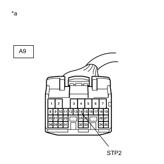
*a Front view of wire harness connector
(to Skid Control ECU Assembly)
Disconnect the A9 skid control ECU assembly connector.
-
Measure the voltage according to the value(s) in the table below.
Standard Voltage Tester Connection Condition Specified Condition A9-14 (STP2) - Body ground Brake pedal depressed 8 to 14 V Result Proceed to OK NG
OK
REPLACE SKID CONTROL ECU ASSEMBLY for RHD: Click here
REPLACE SKID CONTROL ECU ASSEMBLY for LHD: Click hereNG
CHECK HARNESS AND CONNECTOR (SKID CONTROL ECU ASSEMBLY - NO. 3 SEMICONDUCTOR POWER INTEGRATION ECU) Click here
-
-
READ VALUE USING GTS (STOP LIGHT OUTPUT SIGNAL AND STATUS OF STOP LIGHT FUSE)
-
Disconnect the center stop without harness light assembly connector.
-
Using the GTS, check the Data List "Stop Light Output Signal" and "Status of Stop Light Fuse" with the brake pedal operated.
Body Electrical > Power Integration No.3 > Data ListTester Display Measurement Item Range Normal Condition Diagnostic Note Stop Light Output Signal Stop light output condition ON or OFF ON: Stop light is on
OFF: Stop light is off
Stop lights blink during emergency brake signal control Status of Stop Light Fuse Stop light fuse condition Disconnect or Connect Disconnect: Fuse shut off
Connect: Fuse not shut off
-
Body Electrical > Power Integration No.3 > Data ListTester Display Stop Light Output Signal Status of Stop Light Fuse OK Brake pedal operation Data List Display Condition Stop Light Output Signal Status of Stop Light Fuse Brake pedal depressed ON Connect Result Brake pedal operation Data List Display Condition Result Stop Light Output Signal Status of Stop Light Fuse Brake pedal depressed ON Connect A OFF Disconnect B
A
REPLACE CENTER STOP WITHOUT HARNESS LIGHT ASSEMBLY Click here
B
READ VALUE USING GTS (STOP LIGHT OUTPUT SIGNAL AND STATUS OF STOP LIGHT FUSE) Click here
-
-
CHECK HARNESS AND CONNECTOR (SKID CONTROL ECU ASSEMBLY - NO. 3 SEMICONDUCTOR POWER INTEGRATION ECU)
-
Disconnect the A9 skid control ECU assembly connector.
-
Disconnect the X99 No. 3 semiconductor power integration ECU connector.
-
Measure the resistance according to the value(s) in the table below.
Standard Resistance Tester Connection Condition Specified Condition A9-14(STP2) - X99-1(OUT) Always Below 1 Ω A9-14(STP2) or X99-1(OUT) - Body ground Always 10 kΩ or higher Result Proceed to OK NG
OK
REPLACE NO. 3 SEMICONDUCTOR POWER INTEGRATION ECU Click here
NG
REPAIR OR REPLACE HARNESS OR CONNECTOR
-
-
READ VALUE USING GTS (STOP LIGHT OUTPUT SIGNAL AND STATUS OF STOP LIGHT FUSE)
-
Disconnect the X64 light wire connector.
-
Using the GTS, check the Data List "Stop Light Output Signal" and "Status of Stop Light Fuse" with the brake pedal operated.
Body Electrical > Power Integration No.3 > Data ListTester Display Measurement Item Range Normal Condition Diagnostic Note Stop Light Output Signal Stop light output condition ON or OFF ON: Stop light is on
OFF: Stop light is off
Stop lights blink during emergency brake signal control Status of Stop Light Fuse Stop light fuse condition Disconnect or Connect Disconnect: Fuse shut off
Connect: Fuse not shut off
-
Body Electrical > Power Integration No.3 > Data ListTester Display Stop Light Output Signal Status of Stop Light Fuse OK Brake pedal operation Data List Display Condition Stop Light Output Signal Status of Stop Light Fuse Brake pedal depressed ON Connect Result Brake pedal operation Data List Display Condition Result Stop Light Output Signal Status of Stop Light Fuse Brake pedal depressed ON Connect A OFF Disconnect B
A
REPLACE LIGHT WIRE Click here
B
-
-
READ VALUE USING GTS (STOP LIGHT OUTPUT SIGNAL AND STATUS OF STOP LIGHT FUSE)
-
Disconnect the A9 skid control ECU assembly connector.
-
Using the GTS, check the Data List "Stop Light Output Signal" and "Status of Stop Light Fuse" with the brake pedal operated.
Body Electrical > Power Integration No.3 > Data ListTester Display Measurement Item Range Normal Condition Diagnostic Note Stop Light Output Signal Stop light output condition ON or OFF ON: Stop light is on
OFF: Stop light is off
Stop lights blink during emergency brake signal control Status of Stop Light Fuse Stop light fuse condition Disconnect or Connect Disconnect: Fuse shut off
Connect: Fuse not shut off
-
Body Electrical > Power Integration No.3 > Data ListTester Display Stop Light Output Signal Status of Stop Light Fuse OK Brake pedal operation Data List Display Condition Stop Light Output Signal Status of Stop Light Fuse Brake pedal depressed ON Connect Result Brake pedal operation Data List Display Condition Result Stop Light Output Signal Status of Stop Light Fuse Brake pedal depressed ON Connect A OFF Disconnect B
A
REPLACE SKID CONTROL ECU ASSEMBLY for RHD: Click here
REPLACE SKID CONTROL ECU ASSEMBLY for LHD: Click hereB
CHECK HARNESS AND CONNECTOR (SKID CONTROL ECU ASSEMBLY - NO. 3 SEMICONDUCTOR POWER INTEGRATION ECU) Click here
-
-
CHECK HARNESS AND CONNECTOR (SKID CONTROL ECU ASSEMBLY - NO. 3 SEMICONDUCTOR POWER INTEGRATION ECU)
-
Disconnect the A10 skid control ECU assembly connector.
-
Disconnect the X99 No. 3 semiconductor power integration ECU connector.
-
Measure the resistance according to the value(s) in the table below.
Standard Resistance Tester Connection Condition Specified Condition A10-16 (STP) - X99-10 (STP) Always Below 1 Ω A10-16 (STP) or X99-10 (STP) - Body ground Always 10 kΩ or higher Result Proceed to OK NG
OK
REPLACE NO. 3 SEMICONDUCTOR POWER INTEGRATION ECU Click here
NG
REPAIR OR REPLACE HARNESS OR CONNECTOR
-
-
CHECK HARNESS AND CONNECTOR (SKID CONTROL ECU ASSEMBLY - NO. 3 SEMICONDUCTOR POWER INTEGRATION ECU)
-
Disconnect the X99 No. 3 semiconductor power integration ECU connector.
-
Measure the resistance according to the value(s) in the table below.
Standard Resistance Tester Connection Condition Specified Condition X99-1 (OUT) - A9-14 (STP2) Always Below 1 Ω X99-1 (OUT) or A9-14 (STP2) - Body ground Always 10 kΩ or higher Result Proceed to OK NG
OK
REPLACE NO. 3 SEMICONDUCTOR POWER INTEGRATION ECU Click here
NG
REPAIR OR REPLACE HARNESS OR CONNECTOR
-