OIL COOLER INSTALLATION
PROCEDURE
-
INSTALL OIL COOLER BRACKET
-
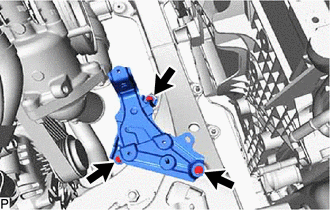
Install the oil cooler bracket with the 3 bolts.
- Torque:
- 6.0 N*m { 61 kgf*cm, 53 in.*lbf }
-
-
INSTALL OIL COOLER ASSEMBLY
-
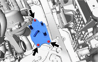
Install the oil cooler assembly with the 3 bolts.
- Torque:
- 6.0 N*m { 61 kgf*cm, 53 in.*lbf }
-
-
INSTALL WIRE HARNESS CLAMP BRACKET (for LHD)
-
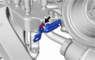
Install the wire harness clamp bracket with the nut.
- Torque:
- 10 N*m { 102 kgf*cm, 7 ft.*lbf }
-
-
CONNECT WIRE HARNESS (for LHD)
-
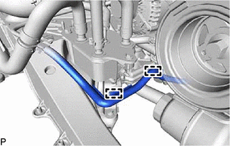
Attach the 2 clamps and connect the wire harness.
-
-
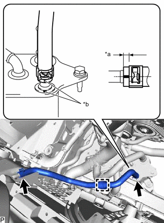
CONNECT RADIATOR HOSE SUB-ASSEMBLY
-
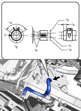
*a 2.0 to 5.0 mm (0.0787 to 0.197 in.) *b Paint Mark *c Permissible range for paint mark position *d Outside permissible range for paint mark position *e Clamp Range 120° *f Front of vehicle *g Left side of vehicle Connect the radiator hose sub-assembly to the oil cooler assembly, and slide the hose clip to secure the hose.
Note
-
The hose clip claw position is within the range shown in the illustration.
-
Do not deform the oil cooler assembly.
-
Install the radiator hose sub-assembly so that its paint marks are within the allowable range (3 paint lines) of the paint marks of the oil cooler assembly.
-
Water or washer fluid can be used to assist with inserting the hose, however when using liquid other than water, dilute it to 50% concentration or less before use.
-
When installing the radiator hose sub-assembly, do not twist the radiator hose sub-assembly
-
-
-
INSTALL NO. 1 OIL COOLER OUTLET HOSE
-
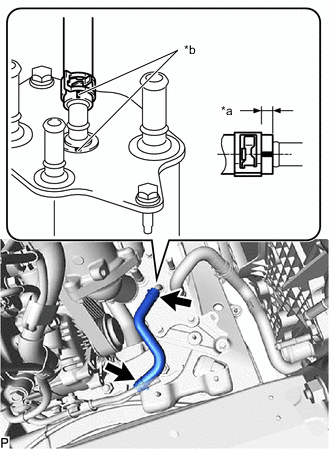
*a 2.0 to 7.0 mm (0.0787 to 0.276 in.) *b Paint Mark Install the No. 1 oil cooler outlet hose to the No. 1 oil cooler outlet tube and oil cooler assembly, and slide the 2 hose clips to secure the hose.
Note
-
Do not deform the oil cooler assembly.
-
When connecting the hose, align with the colors and positions of the paint mark before connecting.
-
When installing the No. 1 oil cooler outlet hose, do not twist the No. 1 oil cooler outlet hose.
-
-
-
INSTALL NO. 1 OIL COOLER INLET HOSE
-
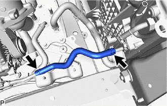
Install the No. 1 oil cooler inlet hose to the radiator assembly and No. 1 oil cooler inlet tube, and slide the 2 hose clips to secure the hose.
Note
-
When connecting the hose, align with the colors and positions of the paint mark before connecting.
-
When installing the No. 1 oil cooler inlet hose, do not twist the No. 1 oil cooler inlet hose.
-
-
-
CONNECT NO. 3 RADIATOR HOSE
-
INSTALL WATER BY-PASS HOSE
-
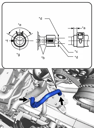
*a 2.0 to 5.0 mm (0.0787 to 0.197 in.) *b Paint Mark *c Permissible range for paint mark position *d Outside permissible range for paint mark position *e Clamp Range 120° *f Front of vehicle *g Left side of vehicle Install the water by-pass hose to the oil cooler assembly and No. 3 radiator hose, and slide the 2 hose clips to secure the hose.
Note
-
The hose clip claw position is within the range shown in the illustration.
-
Do not deform the oil cooler assembly.
-
When installing the water by-pass hose, do not twist the water by-pass hose.
-
Water or washer fluid can be used to assist with inserting the hose, however when using liquid other than water, dilute it to 50% concentration or less before use.
-
Install the radiator hose sub-assembly so that its paint marks are within the allowable range (3 paint lines) of the paint marks of the oil cooler assembly.
-
-
-
INSTALL NO. 4 TRANSMISSION OIL COOLER HOSE
-
*a 2.0 to 7.0 mm (0.0787 to 0.276 in.) *b Paint Mark Install the No. 4 transmission oil cooler hose to the radiator assembly and oil cooler assembly, and slide the 2 hose clips to secure the hose.
Note
-
Do not deform the oil cooler assembly.
-
When connecting the hose, align with the colors and positions of the paint mark before connecting.
-
When installing the No. 4 transmission oil cooler hose, do not twist the No. 4 transmission oil cooler hose.
-
-
Attach the clamp and connect the No. 4 transmission oil cooler hose to the water by-pass hose.
-
-
INSTALL RADIATOR RESERVE TANK ASSEMBLY
-
INSTALL INTAKE AIR CONNECTOR PIPE
-
INSTALL AIR CLEANER WITH ELEMENT ASSEMBLY RH
-
INSTALL AIR CLEANER HOSE ASSEMBLY
-
INSTALL RADIATOR SUPPORT TO CROSS MEMBER BRACE SUB-ASSEMBLY RH
-
ADD ENGINE COOLANT
-
INSTALL LOWER RADIATOR AIR DEFLECTOR
-
INSTALL RADIATOR SUPPORT TO FRAME SEAL RH
-
INSTALL RADIATOR SUPPORT TO FRAME SEAL LH
-
INSTALL V-BANK COVER SUB-ASSEMBLY
-
ADD AUTOMATIC TRANSMISSION FLUID
-
ADJUST AUTOMATIC TRANSMISSION FLUID
-
INSPECT FOR COOLANT LEAK
-
INSTALL STRUT BAR BRACKET SUPPORT SUB-ASSEMBLY
-
INSTALL NO. 2 ENGINE UNDER COVER ASSEMBLY
-
INSTALL NO. 1 ENGINE UNDER COVER ASSEMBLY
-
AFTER FILLING TRANSMISSION
-
ATF THERMAL DEGRADATION ESTIMATE RESET
Note
Approximately 50% or more of the ATF has been replaced during a repair of the transmission or a similar operation.